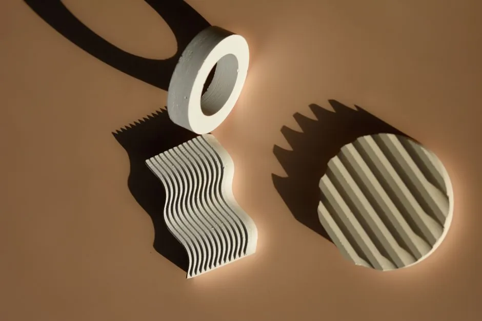
Three disc pack geometries dominate industrial disc coupling installations: straight-sided (constant cross-section), scalloped (material relieved at the bolt-circle area), and link-type (segmented laminates bolted together). Each geometry maps to a different torque, misalignment, and serviceability envelope, and the wrong choice shows up as premature fatigue cracking or coupling wind-up within months of commissioning [S2][S3].
Straight-sided packs are still the default in API 610 / API 671 process pumps and in high-speed compressor trains, where the disc sees a steady torque stream and the alignment program is disciplined. Scalloped packs are the workhorse in motor-to-gearbox and motor-to-pump arrangements where the installer is unlikely to hit the alignment target on the first try. Link-type (also called spacer-link or segmental) packs split the load path across multiple thin links and are most often seen in large turbo-compressor couplings and in marine propulsion, where disc-pack replacement without hub removal matters more than peak torque density [S2][S3][S4].
Geometry and How Each Pack Flexes
A straight-sided disc pack uses a uniform blade width between the inner and outer diameters, so bending strain is distributed evenly around the circumference under misalignment. Removing material at the bolt-circle area to form a scalloped (contoured) profile reduces the cross-section exactly where bending stress concentrates, so the disc accepts a higher angular offset before the outer fibre reaches the same strain level [S4]. Link-type packs replace a single continuous disc with several individual links, each carrying a fraction of the torque, so misalignment is split between the radial pivoting of each link and the elastic bending of the link itself [S2].
Practical implication: a given coupling size in a scalloped configuration typically rates lower in continuous torque than the same size in a straight-sided configuration, because the load-carrying cross-section is smaller. Scalloped geometry is therefore specified for its flexibility per unit torque, not for raw torque throughput, and link-type geometry is specified for serviceability and shock absorption, not for either extreme [S2][S3][S4].
Torque Density, Speed, and Misalignment Capacity
Torque density (Nm per kg of disc pack, or Nm per mm of outer diameter) is the first number to compare when the equipment train is space-constrained. Straight-sided packs set the baseline: the continuous cross-section allows the full blade width to carry load, which is why high-torque-density couplings (Dodge Disc, Kop-Flex, Bibby Turboflex, John Crane Metalflex) are built around straight blades for the heavy-duty ratings [S3].
Link-type packs sit in the middle on torque density but lead on radial and axial stroke: the segmented construction allows individual links to pivot, so the assembly can absorb several millimetres of parallel offset and substantial axial end-float without overstressing any one disc. Speed-wise, all three geometries can be balanced to AGMA 9000 / API 671 balance grades, but the link-type pack's distributed mass usually requires more balance work at the shop to hit the high balance grade demanded by turbomachinery [S2][S3].
Selection Criteria Side by Side
The decision matrix below lines the three geometries up against the four criteria that drive most spec calls. Use it as a quick filter before opening a vendor selection software. [S5]
Geometry vs. criterion: <strong>Torque density</strong> = straight-sided highest, link-type middle, scalloped lowest; <strong>Angular misalignment capacity</strong> = scalloped highest (typically up to 1.5-3.0 degrees per disc pack), link-type middle, straight-sided lowest (often capped near 0.5-1.0 degree per pack); <strong>Serviceability / field replaceability</strong> = link-type highest (individual links can be unbolted), scalloped and straight-sided both require full disc-pack changeout; <strong>Balance grade achievable</strong> = straight-sided best for high-speed API 671 turbomachinery, scalloped similar, link-type requires more correction mass but is feasible to AGMA class 9 or higher [S2][S3][S4].
Two concrete thresholds worth memorising: most API 671 process-pump couplings run straight-sided and stay below 0.5 degree per pack, with peak speeds that demand AGMA balance class 9 or tighter; most general-purpose motor-to-pump couplings run scalloped and accept up to 1.5-2.0 degrees per pack to forgive installation error. If a coupling sees more than 3 degrees of combined misalignment at commissioning, the spec is wrong, not the alignment crew [S2][S3].
Failure Modes Specific to Each Geometry
Straight-sided disc packs fail predominantly by fatigue cracking at the inner diameter (where bending strain peaks under angular offset) and, less commonly, by overload yielding at the bolt holes. Because the strain distribution is symmetric, cracks tend to propagate straight across the blade and a single through-thickness crack usually means complete pack replacement [S3]. Scalloped packs fail in two characteristic patterns: fatigue initiation at the root of the scallop (the relieved section), or, in contaminated or misaligned installations, tearing at the transition radius between the contoured area and the constant-width blade. Cracks at scallop roots travel along the relieved contour, which is why visual inspection of scalloped packs should follow the scallop profile, not a straight radial line [S4].
Link-type packs fail differently again. The most common mode is link-bolt loosening or link-bolt hole elongation, which presents as increased wind-up angle rather than as a visible crack. Because the load is shared, a single failed link does not usually mean catastrophic loss of torque capacity, but it does mean the coupling is now operating above its design load on the surviving links, and continued running is a controlled shutdown, not a normal operating condition [S2]. For related reading on bolt-circle loading and fastener behaviour in rotating equipment, see this comparison of roller vs ball bearing dynamic load rating, which covers the same bore-side load logic.
Installation, Alignment Tolerance, and Spacer Considerations

Straight-sided disc packs reward precision: a coupling spec'd at 0.5 degree per pack should be installed inside 0.1-0.2 degree to leave margin for thermal growth. Scalloped packs are more forgiving and are the right call when the driver and driven equipment sit on different foundations, on settling soil, or on a structure that will see thermal growth well over 10 mm. Link-type packs are most often supplied in spacer configurations (the disc pack sits inside a spacer tube between two hubs), where the disc sees only angular and axial load, not parallel offset, and the spacer length is sized to give the maintenance crew clearance to remove bearings or seals without moving the driver [S2][S3].
Installation note that applies to all three: disc pack bolts must be torqued in a star pattern to the OEM value, and the pack must be visually inspected for correct stacking orientation (alternate inner/outer fingers, marked faces out) before the spacer is slid home. A reversed disc pack halves the misalignment capacity of the coupling, and the failure presents only under load, not at installation [S3][S4].
Standards, Balance, and Sourcing Notes
For process-pump and turbomachinery service, the governing documents are API 610 (centrifugal pumps) and API 671 (couplings), with AGMA 9000 covering balance grades and ISO 1940-1 for rigid-rotor balance. ATEX 2014/34/EU applies when the coupling is installed in a classified area, and disc-pack material upgrades (e.g. 17-4 PH, A286, Inconel 718) are typically required for sour-service NACE MR0175 environments or for elevated-temperature installations above 200 degC. None of these standards prescribe a specific disc geometry, so the choice of straight-sided, scalloped, or link-type is left to the engineer and the OEM's published ratings [S2][S3].
For a broader spec context on coupling-adjacent components and how geometry choices propagate through a rotating train, this overview of saddle vs sunk key for light-duty friction drives covers the same torque-path reasoning at smaller scales. Trackable next signals: revised API 671 balance and inspection clauses, plus the steady migration of new industrial couplings to scalloped profiles as misalignment tolerance becomes a procurement requirement rather than an installation nicety [S3].
Spec-level background on the components involved: circular saw, and dry type transformer.