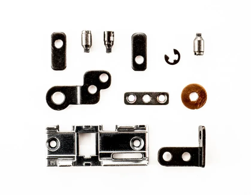
Shafted screw conveyors longer than roughly 10 to 12 ft (3.0 to 3.7 m) need at least one intermediate hanger bearing to keep the coupling shaft from whipping, and standard CEMA grouping places each hanger at 8 to 12 ft (2.4 to 3.7 m) of screw between couplings.
Those numbers are not arbitrary: they come from the CEMA component selection tables, the same tables that bucket materials into bearing groups and tie those groups to allowable spans and screw speeds [S2][S4]. Get the spacing wrong, and the operator pays for it in shaft deflection, premature hanger wear, and material backup around the bearing.
What Sets the Maximum Span Between Hangers
The maximum span between two hanger bearings is the screw length between two adjacent coupling shafts, not the trough length. KWS Manufacturing's installation guide specifies that the hanger bearing is centered on the coupling shaft with the screw turning freely after seating, then the next hanger is positioned so the screw section between couplings sits within the catalog's recommended run [S1].
For standard CEMA stock components on shafts up to 3 7/16 in. diameter, that run is normally 8 to 12 ft (2.4 to 3.7 m), depending on the screw diameter, RPM, and material being conveyed [S2][S4]. Martin's engineering procedure (Step 6) explicitly routes the designer to the hanger bearing selection table after classifying the material, then to a table that maps each bearing group to a permitted span [S4]. Screw Conveyor Corporation's 787F catalog applies the same logic, with component group tables built around the same CEMA pattern [S2].
The practical floor is structural: the coupling shaft between two hangers is an unsupported rotating beam, and once its slenderness ratio and load from the screw flights push its critical speed down toward the operating RPM, the span becomes a vibration problem rather than a wear problem. The 8-12 ft envelope keeps most stock sizes well below that threshold.
Which Screw Conveyor Hanger Style Goes Where
Two hanger geometries dominate the CEMA stock range: the Style 226 (also written 220) and the Style 216. Style 226 uses a single support bar bolted inside the trough, which is the most common configuration in U-trough conveyors because it leaves the cross-section more open for material flow [S5]. Style 216 uses two support bars spaced apart on either side of the bearing; the bar separation gives more resistance to screw sway and to side loads from heavy or lumpy material, at the cost of more obstruction in the trough [S5].
Both styles are split for installation without removing the screw, and both are CEMA-standardized for shaft sizes from 1-1/2 in. up to 3 7/16 in., so a Style 226 from one maker cross-references to another's part number, for example a Martin CHB2203W (1-1/2 in. shaft, wood) is the same part as a KWS HGB226112W or a Conveyors Inc. BX112-W [S5]. Standardized part numbering matters in the field: a 2 in. shaft wood hanger is Martin CHB2204W, KWS HGB2262W, and BX2-W, three brand labels, one component [S5].
Outside the CEMA stock range, Chinese OEMs such as Tongjinjin offer XLR, TLR, XLY, TLY, XLU, and SI hanger families for sectional screw conveyors, with 40 to 60 mm coupling shafts and 19, 20, or 28-tooth splines [S8]. These cover the 6, 9, and 12 in. (150, 225, 300 mm) sectional screw sizes that show up in the Asian bulk-handling market and follow the same multi-hanger layout logic, just on metric shafting.
Material Group Drives Bearing Type and Spacing

CEMA material groups are the upstream input: they classify the bulk solid by abrasiveness, flowability, corrosiveness, and miscellaneous properties, and each group maps to a recommended hanger bearing material [S2][S4]. The four standard hanger bearing materials are white nylon (Nylatron), bronze, hard iron (often drilled for oil lubrication), and wood, with UHMW and ceramic saddles offered for special service [S4][S6].
A typical mapping: mildly abrasive, free-flowing materials (CEMA groups such as grain, plastic pellets, wood chips) get white nylon or wood hangers; abrasive minerals and cement-type materials get hard iron or bronze; high-temperature or corrosive duty pushes the spec toward bronze, ceramic, or specialty alloys [S4][S5]. Hanger material is selected before span is finalized, because the heavier the hanger, and the higher the screw RPM, the shorter the allowable run between bearings for a given shaft size.
For comparison across materials on a single 2 in. shaft, all three stock options (wood, hard iron drilled for oil, and bronze) are stocked in the same Style 226 form factor, so a designer can swap bearing material without changing the spacing rule [S5][S6]. The tradeoff is service life versus contamination risk: hard iron is durable but cannot tolerate product contamination if the line is food-grade, while UHMW and white nylon are food-friendly but wear faster in abrasive service.
Recommended Screw Orientation at Hangers
KWS recommends offsetting the screw flight ends at 180 degrees from each other at intermediate hanger locations, so the flight cut at the bearing does not align on the same side as the flight cut on the next section [S7]. This balances the axial thrust load that the flight helix generates against the hanger, and it reduces the side load that the bearing has to absorb.
The same rule reduces material backup right at the bearing, because the angled flight pair feeds material past the support bar instead of dead-heading against it. In inclined and vertical screw conveyors, this offset becomes more important, because gravity adds a steady axial bias that the hanger has to react [S2][S7].
Common Failure Modes From Wrong Spacing

Three failure modes dominate when spans are pushed too long: coupling shaft whip (visible at operating speed as a bowed section rotating between hangers), accelerated hanger bearing wear on the inboard journal because side load is no longer evenly distributed, and material compaction on the trough floor directly under the bearing where the flight is interrupted [S1][S3].
On long shafted conveyors, the absence of an intermediate hanger is the single most common root cause of coupling shaft fatigue failure, because the coupling shaft is the smallest-diameter rotating member in the driveline and the least tolerant of runout [S3]. KWS installation notes reinforce that the hanger bearing must sit evenly on the coupling shaft and the screw must turn freely after seating, which is the field test that catches a misaligned hanger before the unit is loaded [S1].
A secondary failure is hanger saddle wear on the trough itself, which happens when the bearing is forced to take lateral load the support bars were never designed for. Style 216 with its two-bar support is the spec answer when a Style 226 is sagging under side load, but the better answer is usually one more hanger, not a heavier hanger [S5].
Spacing Rules of Thumb for Stock CEMA Conveyors
For U-trough conveyors in the 6, 9, 12, 14, 16, 18, 20, and 24 in. screw diameter range, the most widely quoted CEMA limit is 10 ft (3.05 m) maximum screw run between hangers, with 8 to 10 ft (2.4 to 3.0 m) being conservative for abrasive service or screws running at the high end of the catalog RPM range [S2][S4]. Sectional flight conveyors on 1-1/2, 2, 2-7/16, 3, and 3-7/16 in. coupling shafts all use the same envelope, because the bearing selection is keyed to shaft size and material group, not to screw diameter alone [S4][S5].
Screw feeders (short, high-torque units under a hopper) typically use the same hanger rules but with a closer span (often 6 to 8 ft, or 1.8 to 2.4 m) because the screw is fully loaded at the inlet and the trough loading is at the high end of the CEMA table [S2]. Vertical screw conveyors and screw-lifts use only an end bearing at the bottom plus the top thrust assembly, no intermediate hangers, because any mid-shaft bearing would interfere with the lifted column of material.
For an engineer's first-pass layout: pick the screw diameter from the capacity table, pick the hanger bearing material from the material classification table, then drop hangers at 8 to 12 ft (2.4 to 3.7 m) centers along the screw length, stepping closer (6 to 8 ft, or 1.8 to 2.4 m) for abrasive or high-RPM service and adding an extra hanger at any transition from horizontal to inclined [S2][S4]. That sequence matches the CEMA 10-step design procedure and avoids re-work after the steel is cut.
Trackable Signals Going Forward
Two follow-on items a spec engineer can monitor: revised CEMA hanger bearing spacing guidance for very large diameter screws (24 in. and above) running at variable-frequency drive (VFD) speeds, and field data on hard-iron versus UHMW wear life under high-temperature cement or fly-ash service. Both are within the scope of the standard CEMA material groups today, but neither is fully covered by the current stock-component catalogs [S2][S4].
For more on the wider mechanical-design tradeoffs that feed into conveyor layout, the selection logic for long-stroke pneumatic cylinders covers related span-versus-deflection thinking that translates directly to long shafted screw conveyors.
Spec-level background on the components involved: ball screw, and lead screw.