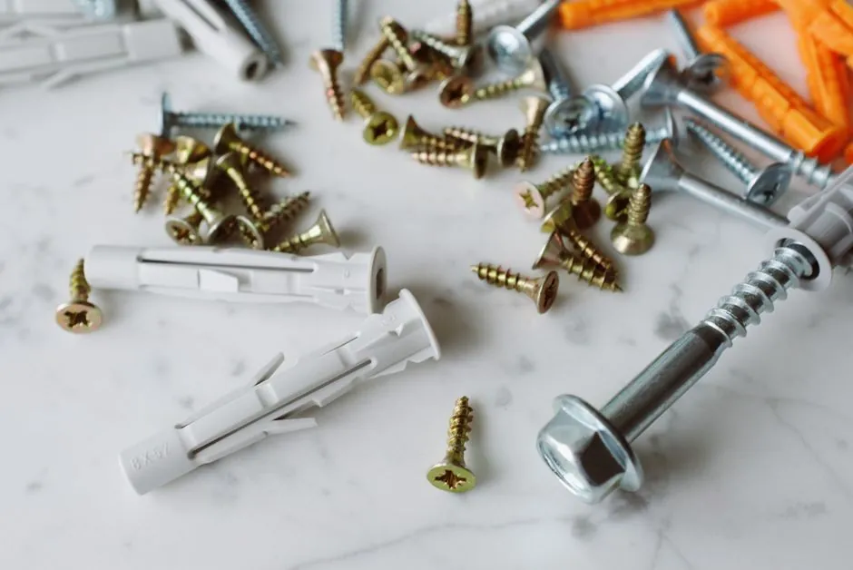
In a screw conveyor the rotating core is a center pipe, typically Schedule 40 or 80, with sectional screw flights welded to it; the small-diameter component that actually passes through hanger bearings and transmits torque between sections is the coupling shaft, not the pipe itself [S1].
Two construction philosophies dominate new builds in 2026: a CEMA-style coupling-shaft assembly where a solid stub shaft is inserted and bolted into each pipe end, and a flanged shaft-to-pipe (pipe-shaft) design where a register-fit coupling plate is welded to the pipe and bolted to a flange on the drive shaft [S1][S2]. The choice governs maintainability, torque rating, and how multi-section conveyors are physically joined on site.
Defining the Two Architectures
The coupling-shaft approach uses a uniform-diameter solid stub, most commonly supplied in CEMA-standardized diameters of 1 1/2", 2", 2 7/16", 3", and 3 7/16", that is inserted into the pipe end and held by 2-bolt or 3-bolt connections set 90 degrees apart [S1]. Standard bolting is 2-bolt; 3-bolt connections are common in heavier or longer sections and share a common bolt pattern so that any 2-bolt or 3-bolt pipe will accept any 2-bolt or 3-bolt shaft of the same diameter [S1].
The pipe-shaft (flanged) design is fundamentally different. KWS describes a coupling plate with a register fit to a drive-shaft coupling flange, intended to simplify alignment and transfer torque through a face-to-face bolted flange rather than through bolts passing through a pipe wall [S2]. The center pipe is not a structural torque-carrying member in the bolted region; instead, the flange and the register fit carry the load, and the pipe simply encloses the flights and material.
Torque Path and Material Choices
Coupling shafts are nearly always made from carbon-steel bar stock, with C1020, C1040, C1045, and C4140 the typical grades; C1020 and C1045 dominate because they are economical, machinable, and adequately hard, while C4140 is reserved for higher-strength duty [S1]. When corrosion or washdown service is specified, 304 and 316 stainless steel are the common upgrades.
Hardening is applied selectively, not across the full shaft. Only the length that runs through a hanger bearing or shaft seal is case hardened, so the bearing surface wears preferentially and the shaft itself survives longer in abrasive service [S1]. Drive shafts, which are highly custom because every gearbox output is different, can also be hardened through the seal area to extend service life; the same selective-hardening logic applies [S1].
Through the flanged pipe-shaft path, torque moves from the gearbox adapter into a drive-shaft flange, across a register-fit coupling plate welded to the pipe, and into the next section. The result is a stiffer joint but one that is less forgiving of mis-assembly; the register fit is the alignment feature that the bolted-flange geometry depends on [S2].
Joining Multiple Screw Sections on Site

Long conveyors are built in sections because a single ultra-long pipe is harder to keep straight, harder to lift, harder to paint and pack, and harder to ship and install; sectional construction also lets a single damaged section be replaced without scrapping the whole assembly [S4]. The penalty is that every internal joint has to transmit torque, so the coupling between sections is a load-bearing component, not a convenience.
In the coupling-shaft layout, field procedure is to drop the coupling shaft into the open end of the pipe, tighten the coupling bolts, then insert the protruding stub into the hanger bearing and clamp the hanger to the trough [S5]. When the joint falls between hangers (a "close coupling"), the same stub can be used in a clocked alignment so the flights are rotationally phased, eliminating the visible step in the helix at the joint [S8].
For pipe-shaft designs, the in-the-field steps are heavier: pipe ends must be aligned so the register fits, flange bolts torqued in pattern, and any gasket or sealant installed. KWS frames this as a benefit for engineered, high-torque lines where repeatability of alignment matters more than quick disassembly [S2].
When Each Design Fits
The coupling-shaft assembly is the right answer for most general bulk-handling duty, including CEMA-class materials in trough screw conveyors built from carbon steel, because parts are interchangeable, hanger bearings are easy to service, and stock components from multiple manufacturers (Martin, KWS, ISC, Screw Conveyor Parts) share a common dimensional standard [S1][S5]. It is also the only practical choice when a screw is divided into many short sections supported on intermediate hangers, since each hanger location needs a stub to ride in the bearing.
The flanged pipe-shaft (KWS-style) design earns its place on long, high-torque, low-hanger lines where the conveyor is essentially a pipe-with-flanges, and where the alignment benefit of a register fit outweighs the loss of CEMA interchangeability [S2]. A 120-page reference like Martin's Stock & MTO catalog still defaults to the CEMA coupling-shaft approach for stock components, while KWS's engineered equipment line uses the flanged connection as a differentiator [S2][S5].
Failure Modes and Field-Repair Reality

Coupling-shaft joints fail by bolt loosening, bearing wear, and stub-shaft wear in the hanger area, and each of those is a localized repair that does not require pulling the entire screw. Hardening the shaft in the bearing/seal zone shifts wear onto the cheaper, replaceable hanger bearing, which is a deliberate wear-part strategy rather than a defect [S1].
Flanged pipe-shaft joints fail differently. Bolt-pattern distortion, gasket set-down, and corrosion at the register fit are the common modes, and correcting them typically requires lifting the pipe and re-aligning the flanges. The US5899319A patent literature on screw couplings describes exactly this problem space: couplings designed to be inserted into hollow pipe shafts and engaged through bolted bushings, where the inner edge of the female bushing controls the engagement length and torque transfer surface [S3].
Comparison Matrix for Specifying Engineers
Across four decision criteria the two designs separate cleanly. On interchangeability, coupling-shaft wins: CEMA-standard diameters 1 1/2" to 3 7/16" and shared 2-bolt / 3-bolt patterns mean any vendor's pipe and shaft will fit any other vendor's pipe and shaft of the same size [S1]. On torque capacity, pipe-shaft with a register-fit flange plate generally carries higher steady-state torque per joint because the load spreads across a flange face rather than a small bolt circle in a pipe wall [S2]. On field serviceability, coupling-shaft is faster: the stub slides into a hanger bearing, the bolts are accessible from outside the pipe, and no flange re-alignment is required [S5]. On alignment repeatability, pipe-shaft is more deterministic: the register fit locates the pipe relative to the drive shaft before the bolts are snugged, removing a variable that coupling-shaft joints only handle by clocked alignment at a close-coupling station [S2][S8].
Connection to Adjacent Mechanical Decisions

Specifying a screw conveyor coupling method rarely travels alone. A close-coupled, clocked joint that removes an intermediate hanger is the same design choice that appears in a rodless magnetic vs tie-rod pneumatic cylinder selection when an actuator must span a long stroke without an intermediate support. The wear-and-replace logic that puts the softer hanger bearing on a hardened coupling shaft is identical in spirit to the wear-element placement used in return-line vs pressure-line hydraulic filtration, where the filter element is the planned sacrificial part. A working spec sheet should also note the related mechanical interfaces, including the shaft coupling that sits upstream of the drive, the shaft collar that locates the gearbox adapter, and the shaft key that locks the drive shaft to the gearbox output, because a coupling-shaft or pipe-shaft choice cascades into all three. [S4]
Trackable signals for the next 6 months: any CEMA Stock Components bulletin that re-states the 1 1/2" to 3 7/16" diameter set with a 2-bolt/3-bolt pattern is a signal that the coupling-shaft interchangeability baseline is unchanged; any KWS or ISC Engineering Guide revision that adds a flanged shaft-to-pipe option for a new CEMA size is a signal that the pipe-shaft architecture is being pushed into smaller diameters, not just engineered long lines [S1][S2][S5][S8].