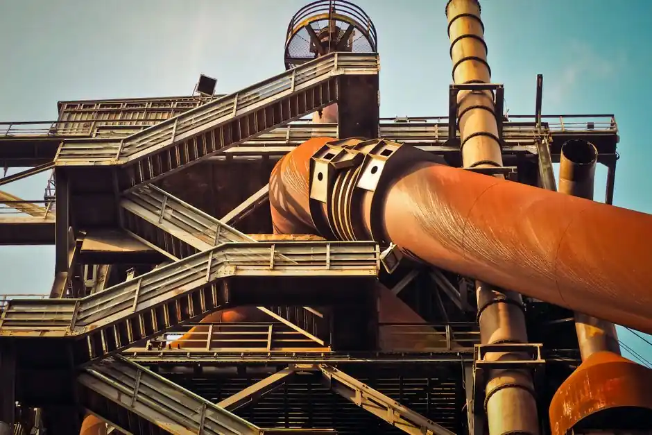
Seamless steel pipe installation is governed by a five-stage workflow of preparation, cutting, welding, fixing, and corrosion protection, with welded carbon structural SMLS pipe typically held to GB/T 8162 or ASTM A106 outer-diameter and wall-thickness tolerances within plus or minus 1 percent [S2].
The scope covers structural, process, and gas-service runs in building frames, machinery supports, bridges, and plant pipe racks, where improper installation drives weld cracking, joint misalignment, and anti-corrosion coating peel-off, the three failure modes that most often trigger rework on a structural carbon-steel job [S2].
Pre-Installation Inspection and Material Verification
Pre-installation inspection rejects any pipe with cracks, folds, delamination, or dents on the visual surface check, and rejects any heat-batch lacking a chemical and mechanical-properties certificate [S2]. Dimensional acceptance uses vernier-caliper measurement of outer diameter and wall thickness against GB/T 8162 or ASTM A106, with deviation controlled within plus or minus 1 percent [S2].
Cleanliness is a hard gate: oil, metal chips, and moisture on the inner or outer surface disqualify the pipe until cleaned, because contamination at this stage propagates into weld porosity and into corrosion under any later coating [S2]. For a primer on the base product, see the seamless steel pipe reference entry.
Cutting, Beveling, and Dimensional Control
Abrasive-wheel or band-saw cutting is the accepted method for structural SMLS, with oxygen cutting explicitly prohibited because the carburized layer left behind embrittles the joint and ruins downstream corrosion performance [S2]. Recommended cut-end geometry is a 30 to 37.5 degree bevel angle, a 1.5 mm root face, and a 1 to 2 mm butt gap reserved for welding shrinkage [S2].
Centerline deviation at the joint is held within 2 mm, rechecked with a laser marking device, and the cut face is polished burr-free with sandpaper or an electric grinder before fit-up [S2]. When the run passes through an expansion joint or trench, the pipe must be inserted into a steel casing first, and any sheep's-horn bend is built from two 75 degree elbows with a sawed groove and a duckbill-shaped main-pipe end, with a bend radius near 2.5 times the pipe diameter [S3].
Welding Procedure and Quality Acceptance
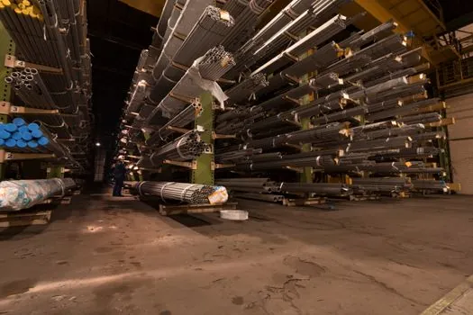
Shielded Metal Arc Welding (SMAW) and Gas Metal Arc Welding (GMAW) are the two methods called out for structural carbon-steel SMLS, with E6010 or E7018 electrodes, welding current of 80 to 130 A, and interpass temperature of 100 to 150 degrees C to prevent cracking [S2]. Joint misalignment is held within 10 percent of wall thickness and within 2 mm, and post-weld inspection combines visual plus Ultrasonic (UT) or Radiographic (RT) methods with an acceptance rate target of at least 98 percent [S2].
For austenitic stainless-steel pipe runs, the joint is typically produced with argon-shielded welding, with the cut and chamfered end deburred before fit-up to preserve sealing and corrosion performance [S1][S5]. Threaded connections remain common on smaller-diameter carbon SMLS for fire and utility risers: lead oil and hemp on the thread, two pipe wrenches used in opposition, and a final exposed thread of 2 to 3 buckles past the fitting as a visual torque-confirmation mark [S3].
Support Spacing, Alignment, and Thermal Compensation
Horizontal structural SMLS runs are supported every 3 to 4 m to prevent sagging, vertical runs use hangers or clamps with limiting rings at joints, and seismic zones switch to elastic damping supports to absorb vibration [S2]. For stainless steel systems, support selection matches pipe diameter, route direction, and load, with stainless-steel brackets with nuts, rod-type clamps, and single clamps the three typical hardware families [S4].
Thermal expansion on stainless runs is calculated as Delta L equals alpha times L times Delta T, using an alpha of 0.0173 mm per meter per degree C, with Type II U-shaped loops, Z-type offsets, cross compensators, ring loops, and bellows expansion joints (for DN32 and larger) as the standard compensation options [S4]. Bends and bypasses in compressed-air networks are themselves pressure-drop sources, so reducing in-line diameter reductions and keeping drops close to the point of use are the two layout rules that most often separate a reliable system from a high-Delta-P one [S5].
Press-Fit Spacing, Elbow Geometry, and Wall Penetrations
Press-fit stainless systems require minimum spacing between couplings and elbows to absorb the minor deformation that the press operation introduces; for DN15 to DN25 the minimum spacing is 20 mm, DN32 to DN50 is 40 mm, and DN65 to DN100 is 60 mm [S4]. Elbow combination safety dimensions scale with diameter: a DN100 90 degree elbow needs 355 mm of makeup length, while a DN15 90 degree needs only 54 mm, and a 45 degree elbow at the same DN100 needs 320 mm [S4].
Where pipe passes through trenches, foundations, walls, and floors, sleeves or casings protect the pipe and avoid hidden contact with concrete or aggressive substrates, and the network must never be encased in a hard solid mass so that maintenance and replacement remain possible [S4][S5]. For larger 3 inch (76 mm) and 4 inch (101 mm) crimp-coupled runs, the lug pattern is specified: minimum 6 lugs for the 76 mm pipe and 7 lugs for the 101 mm pipe, with no overlap of lugs along the barrel [S5].
Anti-Corrosion Protection and Field Acceptance
Anti-corrosion coating integrity is the single largest cause of long-term SMLS field failure when installation is sloppy, because a peeled coating exposes a seamless substrate that has no longitudinal weld seam to slow the resulting external corrosion [S2]. Surface preparation to remove oil, scale, and moisture precedes any coating, and the recommended coating system is matched to the service environment rather than the cheapest available option.
A six-monthly inspection cadence on stainless process lines catches joint weepage and external corrosion before they become leaks, and an industrial hose comparison is often useful at hose-to-pipe transition points where vibration concentrates stress. For the connection hardware on threaded and flanged joints, washer and bolt selection directly affects joint relaxation, and the spring washer selection reference covers the load-match criteria for those components.
Where Standard SMLS Installation Fails and When to Escalate
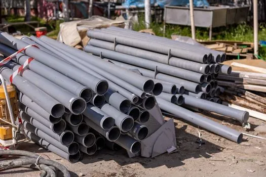
Three failure modes drive most field rework: weld cracking from excessive heat input or low interpass temperature, joint misalignment beyond the 2 mm plus 10 percent wall tolerance, and anti-corrosion layer peeling caused by surface contamination or impact during handling [S2]. When any of these are observed, the corrective action is to cut out the affected section, re-prep the bevel, and requalify the weld with UT or RT rather than to patch in place, because patch welds on loaded structural SMLS rarely meet the 98 percent post-weld acceptance target [S2].
Escalation to a specialist is warranted when the run is a gas main in a high-rise (Type II or bellows compensation preferred), when the pipe is specified to a higher than standard pressure class, or when the route crosses a seismic zone that demands elastic damping supports rather than fixed hangers [S2][S4]. For broader material context on the stainless supply chain that feeds these installations, the stainless-steel signal brief tracks the 2026 price and capacity picture, which directly affects lead time on large SMLS orders.
Two signals to track next: the revision status of GB/T 8162 and ASTM A106 editions, which set the dimensional baseline for any structural SMLS order, and the E7018 electrode supply chain, because E7018 low-hydrogen stock remains the field bottleneck on most structural carbon-steel SMLS jobs through 2026.
Spec-level background on the components involved: linear guide, and crossed roller guide.