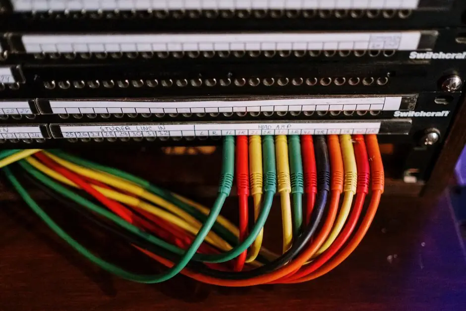
Up to 32 RFID-coded safety interlock switches can be daisy-chained on a single 4-wire M12 trunk with T-adapters and an end plug while still meeting PL e per EN ISO 13849-1 and SIL 3 per EN IEC 62061, a limit cited across multiple vendor product lines [S1][S2][S4][S5].
In-series diagnostics (ISD) is the differentiator: each node reports its own state on the same cable that carries the safety signal, so the safety relay at the end of the chain can identify which door is open, which actuator is mismatched, or which node has an internal fault, without breaking the PL e claim [S1][S2][S4].
Why mechanical-contact series chains lose performance level
When door switches with mechanical contacts are connected in series, fault diagnostics become significantly less effective, which makes it difficult to determine the achievable performance level [S3]. The real-world diagnostic coverage (DC) of such chains often falls below 60%, dropping the achievable level from PL e to PL c even when the same parts were specified as PLe standalone [S3].
The root cause is fault concealment, a category formalised in ISO/TR 24119 and addressed in EN ISO 14119, section 8.6 (logic series connection of interlocking devices) [S3]. EN ISO 13849-1 requires Cat. 3 and Cat. 4 systems to detect every first fault without impairing the protective function, so a chain that can hide a cross-circuit or a welded contact cannot be classified as Cat. 3 and therefore cannot reach PLe, even if DC nominally exceeds 60% [S3]. Practical guidance on the dual-channel wiring that exposes these faults sits in this dual-channel safety relay wiring with cross-fault detection reference.
What ISD actually changes in the chain
ISD puts an electronic, OSSD-class output on every node and routes a non-safety diagnostic channel alongside the two safe signals, so each switch reports its door position, actuator code validity, and internal health to the safety module at the end of the chain [S1][S2][S4]. Banner's SI-RF series implements this as a cascade of up to 32 sensors on a standard 4-wire cable with M12 connectors, T-adapters, and an end plug, keeping wiring to a trunk-and-drop topology [S2].
ifm makes the same 32-node claim and notes that series connection is achieved without losing safety integrity, with clearly visible LEDs on each node showing operating status and diagnostics [S1]. Pizzato Elettrica's NG series goes further, allowing mixed chains that combine door-lock sensors (NG), stainless-steel safety hinges (HX BEE1), and transponder sensors (ST series) in the same series, all while maintaining PL e and SIL 3 [S4][S5]. A useful companion read on the OSSD input side is this OSSD test-pulse filtering and input compatibility guide, since ISD nodes generate the same test-pulse pattern that any OSSD-input safety relay must tolerate.
Selection criteria: RFID-coded vs magnetic-coded vs mechanical
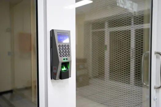
Three interlock families compete in this space, and the series-wiring decision is driven by what you need the chain to tell you. The table below lines them up against the four criteria that matter on a multi-door machine: achievable PL in a 32-node chain, per-node diagnostics, tamper resistance, and actuator-code variety. [S1]
RFID-coded switches with ISD: PL e / SIL 3 maintained at 32 nodes in series, per-node diagnostics including door ID and fault type, high-level coded actuator per EN ISO 14119 with millions of code combinations, typically rated to PLe / SIL 3 standalone as well [S1][S2][S4][S5]. Magnetically coded switches: also series-connectable and can still identify which door is open, lower-cost alternative, mountable out of sight behind non-ferrous material, but lower tamper resistance than RFID because the magnetic field itself can be mimicked with a simple magnet [S1]. Mechanical-contact switches: can be series-wired, but DC commonly drops below 60% in the chain, fault concealment violates EN ISO 13849-1 Cat. 3/4 requirements, and the achievable level frequently collapses to PL c regardless of standalone rating [S3].
Wiring topology, connectors, and what the safety module sees
The standard topology is a 4-wire M12 trunk: two OSSD safety signals plus two for power and the ISD diagnostic return, broken out at each door with a T-adapter and terminated with an end plug at the final node [S2]. Pizzato specifies two safe inputs and two safe outputs per NG switch, so the chain is closed-loop OSSD, with the safety module (Pizzato CS series or any equivalent OSSD-input safety relay / safety PLC) evaluating the outputs of the last switch [S4][S5].
Push-in spring-operated connections on the NG series speed panel-side wiring, and the through-hole actuator entry plus diaphragm seal lets the device pass both IP67 per IEC 60529 and IP69K per ISO 20653 (100 bar water jets at 80 °C) [S4][S5]. The 32-node limit is a vendor-validated ceiling, not a standard-mandated maximum, so cascading beyond 32 requires re-validation by the system integrator rather than a direct cite of EN ISO 14119. The mechanical-side equivalent of this kind of chain decision, where a component choice cascades into a wiring topology, is covered in this saddle vs sunk key comparison, a useful pattern when justifying why a specific node count and connector layout was chosen.
Real use cases and where ISD pays back

Long machinery with many access doors, robotic cells with perimeter fences broken into 8-16 hinged panels, and palletiser guard lines with mixed doors, hinges, and transponder sensors are the typical ISD targets, because wiring each door back to the panel individually would be uneconomic and a single homerun cable with T-drops is far cheaper to install [S1][S2][S4]. Mixed chains are explicit on the NG platform: one trunk can carry NG door locks, HX BEE1 stainless-steel safety hinges, and ST-series transponder sensors together without losing the PL e / SIL 3 claim, which removes the historical objection that you had to split different switch families into separate safety zones [S4][S5].
For the broader machine-safety wiring context, the Cat 3 vs Cat 4 E-stop safety relay decision guide lines up the upstream relay selection against the same fault-detection rules that govern whether an ISD chain is acceptable. On heavier equipment where a guard also has to hold a door closed against process forces, the NG's FZh = 7500 N holding force and F1max = 9750 N breaking force put it among the highest values on the market, and the same series-wiring claim of 32 nodes at PL e / SIL 3 holds [S4][S5].
Limitations, failure modes, and what to verify
ISD does not eliminate the need to verify the end-of-chain safety module: the chain is only PL e / SIL 3 if the evaluating module is itself rated for that level and accepts OSSD inputs, and any 4-wire segment that is mis-wired (e.g. ISD return left floating without the end plug) typically forces the whole chain into a safe-state stop [S1][S2][S4]. Cross-circuit faults between the two OSSD lines remain the classic pitfall, and on mechanical-contact chains they are precisely the failure mode that drops DC below 60% and pulls the chain out of Cat. 3 [S3].
Other constraints worth tracking: the 32-node limit is a vendor-validated figure for the cited families, not a universal EN ISO 14119 ceiling, and mixing in non-listed devices voids the PL e claim unless the combination is explicitly re-validated by the manufacturer [S4][S5]. Actuator coding on the NG series is high-level per EN ISO 14119 with millions of combinations, so a bypass attempt with a foreign actuator of the same family fails, but this only holds if each node is taught to its own actuator at commissioning [S4][S5]. Environmentally, the NG devices are rated to IP67 (IEC 60529) and IP69K (ISO 20653, 100 bar, 80 °C) for washdown areas, but dust-heavy sites still rely on the through-hole dust path and diaphragm seal to keep the actuator bore clear [S4][S5].
Track these signals next: confirm whether your target safety module's OSSD input filter accepts the test-pulse width emitted by the chosen ISD family, request the manufacturer's series-connection validation report for the specific mixed-device count you plan to run, and watch for EN ISO 14119 and ISO/TR 24119 updates that may formalise the 32-node ceiling as a standard rule rather than a vendor derating.
Spec-level background on the components involved: wiring duct, pressure transmitter, and flow meter.