
High-torque shaft keys are commonly produced from medium-carbon steels such as AISI 1045 (C45 / 45#) with tensile strength in the 570–700 MPa band after quenching and tempering, while alloy grades like AISI 4140 and 4340 reach UTS up to 1000 MPa for heavy-duty drives [S4][S2].
Selection is governed by three constraints: the key must equal the shaft in strength and hardness so it fails as the sacrificial element, the material must accept case hardening or through-hardening to 28–35 HRC, and the section must comply with BS 4235, ASME B17.1, or DIN 6892 dimensional envelopes [S1][S4].
Material Grades and Property Targets
Plain-carbon grades 40C8, 45C8, 50C4 and 50C12 cover ordinary transmission shafts, with 45C8 (AISI 1045) the most common pairing for general-duty keys because it machines cleanly and can be heat-treated to roughly 570–700 MPa UTS [S3][S2].
When service torque pushes beyond the safe shear capacity of a C45 key, designers step up to alloy steels. AISI 4140 (chrome-moly) and AISI 4340 (nickel-chrome-moly) deliver UTS up to 1000 MPa along with markedly better fatigue endurance, and are the default choice for mining, marine propulsion, and large gear drives [S4].
Stainless variants (AISI 316, 17-4 PH) and brass appear only where corrosion or galvanic isolation outweighs torque capacity, since their shear ratings sit well below quenched 4140 and they are not interchangeable with alloy-steel keys in high-torque assemblies [S4].
Mechanical Property Comparison for Key Selection
The table below lines the practical options up against the four criteria that matter when a key must carry high torque: typical UTS, achievable surface hardness after heat treatment, machinability/availability, and the service band where the grade is normally specified. [S1]
AISI 1045 (C45) is the workhorse: 570–700 MPa UTS, 28–35 HRC after induction or flame hardening, stocked in square and rectangular key stock, and used in the bulk of industrial gearboxes, pumps, and motor couplings up to moderate torque [S2][S4].
AISI 4140 raises UTS to roughly 850–1000 MPa with through-hardenability to 28–40 HRC, costs more and is harder to machine, but is preferred for large mill drives, crusher shafts, and heavy conveyors where a C45 key would shear prematurely [S4].
AISI 4340 tops the list with UTS near 1000 MPa, superior impact toughness down to roughly -40 °C service, and is reserved for the most demanding high-torque hubs such as turbine-driven compressors and naval gearboxes [S4].
Woodruff and half-moon keys in 1045 are limited to light-load or tapered-shaft applications because the disc-cutter keyway cuts deeply into the shaft and concentrates stress, dropping the effective torque capacity well below a parallel key of the same nominal width [S2].
Heat Treatment, Hardness, and the Match-to-Shaft Rule
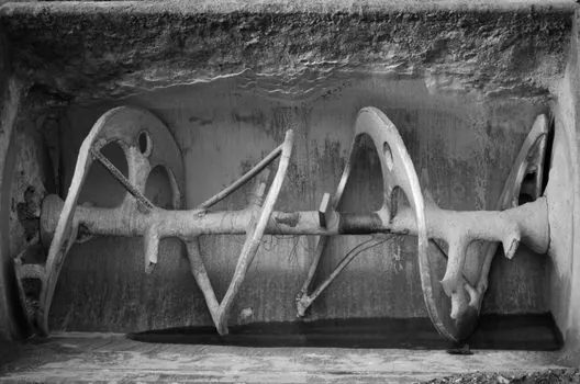
Hardness matching is the single most-cited rule in shaft-key practice: to keep the key acting as the designed sacrificial element, specify key material with the same strength and hardness as the shaft and hub, otherwise the softer member yields and the joint loses its concentric fit [S7].
Typical target is 28–35 HRC on the key side faces, achievable by through-hardening and tempering 4140 or by induction-hardening 1045 to a 1.5–3 mm case depth, which keeps the core tough enough to absorb shock loads without brittle fracture [S4].
Excessively hard keys (above ~40 HRC) combined with a softer shaft invite a different failure mode: the keyway walls crush, the key rocks, and the joint loses preload, so a matched-hardness pairing of 1045 to 1045 or 4140 to 4140 is preferred over a one-sided upgrade [S7].
Key Geometry, Standards, and Torque Capacity
Standards BS 4235, ASME B17.1, and DIN 6892 set the width, height, length, corner-radius, and tolerance tables for parallel keys, with the conventional rule that key width w is roughly one-quarter of shaft diameter d for shafts from about 20 mm up to the 500 mm upper end of standard transmission shaft sizes [S4][S3].
Standard transmission shaft diameters step from 25–60 mm in 5 mm increments, then 60–110 mm in 10 mm steps, 110–140 mm in 15 mm steps, and 140–500 mm in 20 mm steps, with stock shaft lengths of 5 m, 6 m, and 7 m. These stepped sizes drive the matching key-size chart a designer pulls from [S3].
The classic shear-capacity check is T = w × L × τ_allowable × d / 2, where τ_allowable is roughly 0.4 × UTS for a static load and is derated by a fatigue factor for reversing or pulsating torque, and the crushing check compares hub-keyway projected area against the same torque [S2][S4].
For very high torque, parallel keys fall short and the joint moves to splines, involute serrations, or tapered keys with a 1:100 slope that preload under assembly, since the side-bearing area of a single parallel key cannot be made large enough without an unreasonably long hub [S2][S6].
Failure Modes and Limits in Service
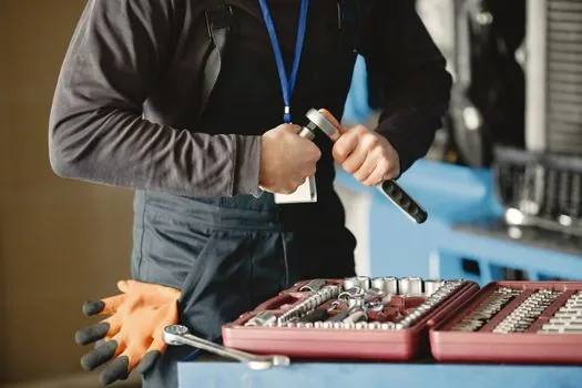
Documented key failure modes under torque load include key shear, keyway crushing on the hub or shaft side, and fatigue cracking that initiates at the keyway corner stress concentration, with the corner radius and fit tolerance deciding which mode dominates [S5].
Square-end parallel keys give more side contact area but are harder to install, while round-end (Form A) keys drop bearing stress because they seat against the natural radius left by an end mill, at the cost of slightly reduced contact length; sled-runner and gib-head profiles exist mainly to ease field removal [S1].
Woodruff keys are explicitly limited to light-load connections because the disc-cutter slot weakens the shaft, and tangent keys are called out for heavy-duty applications where the key sits in a relieved seat and transmits load through a wedging action rather than side bearing [S2][S6].
A practical anti-failure checklist: keep the key harder than the mating keyway edges by no more than about 5 HRC, specify a filleted keyway corner to cut stress concentration, torque the hub fastener to lock the assembly, and pull the joint for NDT inspection at the planned overhaul interval [S5][S7].
Application Fit and Adjacent Selection
High-torque keyed joints are most common in construction machinery and equipment such as excavator swing drives, crusher shafts, and crane slewing rings, where the shaft key must transmit intermittent peak loads well above the motor's continuous rating. [S2]
Where a key is paired with a flexible coupling or a mechanical seal on the same shaft, the keyseat is usually relocated away from the seal journal to avoid inducing runout that would preload the seal face and shorten seal life.
For high-cycle reversing drives such as rolling-mill spindles, designers often replace a single parallel key with involute splines, which distribute load across multiple teeth and raise fatigue life by an order of magnitude over a comparable key [S4].
Trackable signals to watch on the next specification cycle: revised editions of BS 4235 and DIN 6892 tolerances, broader stocking of pre-cut 4140 key stock in metric sizes, and a continuing shift in heavy-industry drives from single-key to splined connections as torque densities climb.
Background reading: Electromagnetic flow meter datasheet parameters for utility water metering.