
Shell core machines fail in three predictable patterns: core box misalignment, heater/control drift, and wear on hydraulically driven moving parts. A weekly cadence of sensor recalibration, vent/coolant verification, and bearing inspection keeps coated-sand core lines within scrap-rate targets [S1][S6].
Process engineers in iron and non-ferrous foundries run these machines with a typical mix of 95% silica sand, 3–4% urea-formaldehyde resin, and 1–2% hardener, blowing the blend into a heated core box at controlled cure temperatures [S2]. The combination of high-cycle pneumatic shooting and constant heat loading is what makes a disciplined calibration and maintenance program non-optional rather than advisory.
Core Box Alignment and Sensor Recalibration Procedure
Core box misalignment is the single most cited cause of dimensionally out-of-spec shell cores, and it almost always traces back to either seat wear on the locating pins or sensor drift on the cure-cycle thermocouples [S1]. A proper realignment starts with a visual and feeler-gauge check of the core box halves on the machine platen, then a step-by-step check of all position and temperature sensors against a known reference before the machine is returned to production [S1].
For instrument-grade checks, follow the same rinse-and-calibrate discipline used for any wet-bench sensor: rinse the probe twice with deionized water, dry it with a lint-free towel, and calibrate against a standard in the expected operating range, in most cases a 1413 µS/cm conductivity reference for wet-side probes, before re-installing [S5]. A 60–80 °F storage environment, with no direct sunlight or humidity exposure, keeps both handheld meters and bench instruments inside their specified accuracy band [S5]. Acceptance criterion: a position sensor repeatability within the OEM-stated tolerance (typically ±0.1 mm for core box closure) and a thermocouple reading within ±5 °C of a calibrated block at the operating setpoint.
Heating System and Temperature Control Verification
Temperature control failure in a shell core machine shows up as core distortion, under-cured shells with low tensile strength, or scorch marks on the box surface, and the first places to look are the LPG or natural-gas burner orifices, the heating element jackets, and the thermocouple seating in the core box platen [S1][S7]. Blocked air vents and fouled coolant passages are the dominant root cause, so a thermal-side inspection should always include clearing the vents and confirming coolant flow before any controller tuning is attempted [S1].
Where the cure temperature has clearly drifted despite clean passages, the controller and the thermocouple itself, not just the heater, are the next suspects. Thermocouples exposed to the resin vapor and thermal cycling of a shell process degrade faster than the same probe in a green-sand environment, and a swap-out against a recently calibrated reference is the only honest acceptance test [S1]. The standard cure window for phenolic/UF-coated sand is roughly 230–315 °C at the core box surface; cores pulled below that band show low hot strength, while cores pushed above it blister and stick.
Mechanical Wear Inspection: Bearings, Rockers, and Hydraulic Seals
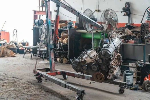
Hydraulically powered core box rocking, used to compact the resin-coated sand before cure, is the most heavily loaded mechanical subsystem on a shell core machine and the one that produces the earliest audible and thermal warning signs [S4]. Operators should listen for any change in the rocker bearing signature, check for oil film failure on the trunnion pins, and inspect gear-mesh backlash against the OEM baseline at every scheduled stop [S1].
For broader mechanical health, run a structured weekly check covering filter condition, lubrication state, hose integrity, and fastener torque on the platen tie bars [S6]. A typical replacement trigger is any bearing showing spalling, any seal with visible extrusion, or any hose with surface cracking under flex; parts at that point belong on the replacement list, not the lubrication list. For a wider maintenance framework, see Pneumatic Cylinder Trade-offs: Specs, Strengths, and Failure Modes, which applies the same symptom-to-cause logic to the pneumatic shooters that feed the core box.
Process Inputs: Sand, Resin, and the Sand-Mix Window
Most "machine" problems in a shell core cell are actually mix problems that show up as scrap, and the operating window is narrow: about 95% silica sand, 3–4% urea-formaldehyde resin, and 1–2% hardener, with the resin and hardener fully homogenized before the sand enters the shooter [S2].
A practical pre-shift check is a moisture cup test on the sand and a hand-fluff of the mix for binder distribution; if the sand clumps or shows visible binder streaks, the sand tank and resin feed are the first places to inspect before the core box itself. Where the mix is correct and the cores still fail, the problem is almost always downstream in the shoot pressure, the cure temperature, or the core box venting, not in the mixer.
Comparison: Shell vs Cold-Box vs Hot-Box Core Equipment Maintenance
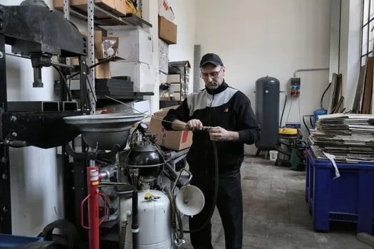
The maintenance profile of a shell core machine is materially different from cold-box and hot-box core equipment, and matching the wrong PM routine to the process is a common source of chronic scrap. On three decision criteria (cure energy, binder chemistry, and primary wear mode), the differences are concrete: [S1]
Shell core machines cure resin-coated sand against a heated metal core box (typically 230–315 °C at the platen), with mechanical wear concentrated in the rocker bearings, platen tie bars, and shooter seals; the binder is a dry phenolic or UF coating activated by heat [S1][S2]. Cold-box coremaking uses a gas-cured (amine or SO2) resin system at room temperature, so its maintenance load shifts toward gas generators, scrubbers, and amine-line seals, with much less thermal stress on the tooling [S4]. Hot-box coremaking sits between the two: a heated core box with a liquid resin system (typically furan/UF with a latent acid catalyst), giving thermal wear similar to shell but with a different binder-cleaning burden inside the box. For a side-by-side view of the equipment and shooter designs themselves, see How to Choose a Shell Core Shooter: Spec-First Selection Guide and Shell Core Shooter Suppliers: 2026 Spec Map and Selection Guide.
When Not to Repair: Replacement and Escalation Triggers
Not every component is worth a rebuild. Escalate to replacement, not repair, when a thermocouple sheath has visible oxidation or has drifted more than the OEM tolerance after a clean recalibration, when a rocker bearing shows spalling or measurable radial play above spec, or when the heater element has dead zones that reappear within a single shift of cleaning [S1][S5]. The same rule applies to electrode-style conductivity and pH probes used in the wet-side QA loop: once the slope falls outside the published specification or the response time stretches noticeably, swap the probe rather than re-calibrate, and never soak a contaminated electrode in solvents or acids for longer than the documented 5–10 minute window [S5].
A practical escalation checklist, to be filled in at every scheduled stop, covers four items: (1) any sensor that fails a two-point calibration check, (2) any bearing or seal flagged by audible noise, oil analysis, or visual scoring, (3) any heater showing a non-uniform temperature map across the core box, and (4) any safety interlock (guards, light curtains, gas-train valves) that does not pass a no-fault trip test. Items 1–3 belong on the spares list; item 4 belongs on the immediate-stop list until the safety circuit is restored. The end goal of the entire PM program, from shell core machine sensor checks to shell core shooter seal replacement, is the same: a repeatable cure window, a stable mix, and a documented pass/fail at every maintenance node.
Closing note: track two signals over the next quarter, the rolling scrap rate per 1,000 cores and the mean time between rocker-bearing replacements; both should trend flat or down, and either trending up is a hard trigger for a full audit of the sand-mix, shoot-pressure, and cure-temperature chain. A deeper reference on the upstream shell molding machine and the related core machine and cold-box core machine families is the natural next read for any team standardizing PM routines across a foundry's core room.