
An industrial shock absorber is a hydraulic or pneumatic energy-dissipation device sized by stroke length, effective mass, energy per cycle (Nm/cycle or J/cycle), and reaction force, typically specified in the 0.5–50 kJ/cycle range for machine-tool and press applications. A gear coupling is a positive-drive, zero-backlash shaft connector sized by torque rating (Nm), bore range, and misalignment capacity, usually expressed in arc-min or mm of parallel/angular offset.
These two components solve orthogonal problems on a drivetrain. A shock absorber sits between a moving mass and a fixed frame, absorbing kinetic energy in a controlled deceleration; a gear coupling sits in-line between two shafts, transmitting torque with torsional rigidity. Specifying one where the other belongs is a common engineering error with measurable cost in downtime and bearing damage, as discussed in our Industrial Shock Absorber Selection gate walkthrough.
Operating Principle: Hydraulic Orificing vs Meshing Gear Teeth
Industrial shock absorbers decelerate a load by forcing viscous fluid through a restrictor passage, converting kinetic energy into heat that the cylinder must dissipate without reaching oil-degradation temperature. Patent literature describes a fail-safe variant where loss of magnet power normally drives damping to maximum, but an auxiliary restrictor passage opens on fault to hold damping near an average, predictable value [S1]. This fail-open geometry matters on vertical axes where full maximum damping on power loss could stall the driven mass mid-stroke.
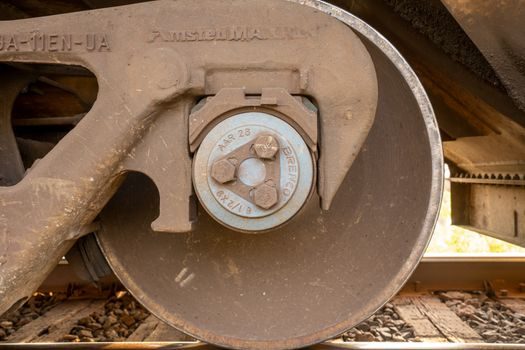
A gear coupling transmits torque through external teeth on one hub meshing with internal teeth on a sleeve, providing positive drive with no angular backlash. Compared to elastomeric couplings, the gear coupling trades damping for torsional stiffness and torque density, which is why it is the default on mill, crane, and turbine drivelines where shaft alignment can be precision-set at install. Misalignment capacity is bounded: typical gear couplings accept 0.1–0.3 mm parallel offset and 0.1°–0.5° angular misalignment, with published derating curves on torque above roughly 0.1° angular.
Spec Gates: Five Numbers That Decide Each Build
For a shock absorber the four hard gates are: effective mass (kg), stroke (mm), energy per cycle (kJ), and cycles per hour. A soft fifth gate is the reaction force curve profile — a sharp peak force overstresses the structure even when total energy is correct. Manufacturers publish energy absorption per cycle with a stated cycle rate, and derate the rating for continuous-duty service because the orifice-restricted hydraulic fluid heats and viscosity falls, shifting the deceleration curve. [S1]
For a gear coupling the gates are: nominal torque (Nm), bore range (mm), speed (RPM), misalignment envelope (mm / arc-min), and service factor relative to the driver. A mismatch on service factor is the most common oversize: a gear coupling selected at 1.0× nominal torque on a peak-loaded drive typically fails in the spline teeth within months. Standard practice is to apply a 1.5–2.0× service factor for reciprocating and reversing drives per AGMA 9002 and equivalent OEM service-factor tables.
Comparison: Shock Absorber vs Gear Coupling on Decision Criteria
On shaft-to-load relationship, the shock absorber is a terminator — it physically anchors the moving mass at end-of-travel; the gear coupling is a passthrough — it adds no axial load and minimal parasitic moment if alignment is inside envelope. [S2]
On maintenance cadence, shock absorbers have a finite seal and gas-charge life measured in cycles (typical industrial units rated 1–2 million cycles to seal rebuild), whereas gear couplings need periodic lubricant refresh on the sleeve teeth (grease every 2000–4000 hours, depending on speed and seal type) and visual spline inspection. On misapplication cost, a wrong shock absorber under-sizes on energy and bottoms out, transmitting a damaging impact force; a wrong gear coupling over-sizes on speed and uncouples via centrifugal disengagement, or under-sizes on torque and shears hub teeth.
Where Each One Belongs — and Where It Does Not
A shock absorber belongs at the end of any linear or rotary motion where a moving mass must be stopped before it hits a hard stop: press slides, gantry Z-axes, cylinder rod-end cushioning, and conveyor transfer stop gates. It does not belong on a continuous-rotating driveline as a vibration damper — that role is filled by elastomeric or disc couplings, not hydraulic absorbers, which would overheat within minutes under continuous cycling. [S3]
A gear coupling belongs on a driveline segment where torque must pass with torsional rigidity and where alignment is precision-controlled: between a gearbox output and a mill pinion, between two motor shafts driving a common load, between a turbine and a gear reducer. It does not belong where high parallel misalignment is expected without periodic re-alignment, where damping of torsional vibration is the primary need, or where the drive must slip under overload — a gear coupling will not slip, it will fail. Elastomeric jaw or tyre couplings are the usual fit for the slip-and-damp use case, as covered alongside the Industrial Shock Absorber Selection gate walkthrough for driveline protection.
Misapplication Case: Specifying a Coupling Where a Shock Absorber Is Required
A common error is fitting a gear coupling between a motor and a screw jack to "absorb end-of-stroke shock." The coupling will transmit the deceleration pulse directly into the motor bearings and the screw thrust bearing, because the gear coupling has no inherent energy absorption path. The correct build is a shock absorber at the end of the screw travel, sized to the screw inertia and the maximum approach velocity, with the coupling then acting only as a torsional passthrough. [S4]
The reverse case — using a hydraulic shock absorber as a shaft connector — does not occur in industrial practice because the geometry is incompatible, but a related error is overspecifying a shock absorber's damping curve to "look smoother" on a datasheet, which then bottoms out under the real load. Patented fail-safe geometries explicitly address this: a fault-state auxiliary restrictor passage holds damping near average so a hard end-stop is avoided even on actuator failure [S1].
Standards, Sourcing and 2026 Sourcing Reality
Shock absorber ratings in the EU are commonly cross-referenced to ISO 9001 manufacturer QC and to in-house test protocols; specific cycle-life and force-curve data is published per model, with no single harmonised international standard governing energy-per-cycle ratings. Gear coupling ratings follow AGMA 9002 for service factors and ISO 9001 for QC, with bore and keyway conformance to ISO 773 / DIN 6885 and concentricity to ISO 1940 balance grades. [S5]
For a 2026 driveline review, walk the VFD Selection Criteria 2026 gate set first, then match the shock absorber and gear coupling to the load and driveline independently — these are two separate buying decisions, not a single component choice. A trackable signal for the rest of 2026: watch for OEM publication of revised cycle-life curves on adjustable hydraulic absorbers, where the fail-open restrictor geometry is gaining traction as a vertical-axis default [S1].
For component-level specifications, see gear pump.