The global Variable Frequency Drive market is projected to grow from USD 24.7 billion in 2025 to USD 32.0 billion by 2030, at a 5.3% CAGR, with AC drives leading by type, pumps/fans/compressors leading by application, and the low-voltage power rating (up to 690 V) holding the largest installed share [S2].
Selection is not a single-spec decision; it is a stack of motor, load, environment, and control constraints that an engineer resolves before a model number is written. The six gates covered below — load profile, power/voltage class, control mode, environment/harmonics, motor pairing, and communication — are the same gates the refrigeration, HVAC, and process OEMs use to cut a BOM [S1][S3].
Load Type and Torque Profile: Constant vs Variable Torque
Variable torque loads (centrifugal pumps, fans, compressors) follow the cube-law affinity between speed and power, which is why a Variable Frequency Drive on a fan shaft can cut energy by 30–50% versus a damper or vane control scheme [S1][S2]. Specification here is a V/Hz or sensorless vector drive in the low-voltage range, sized to motor nameplate kW with no continuous overload margin.
Constant torque loads (conveyors, mixers, extruders, hoists) require 100% rated current across the full speed range, plus a 150% / 60 s overload for breakaway; sensorless or closed-loop vector control is the usual control mode because V/Hz loses torque below 5 Hz [S1]. High-inertia loads (large fans, centrifuges) need extended ramp times and DC-brake or flux-braking enabled to keep DC bus voltage inside the trip band [S1].
Power Rating and Voltage Class
Market segmentation splits VFDs into micro (≤5 kW), low (5–40 kW), medium (40–200 kW), and high (>200 kW) power ratings, with the low-voltage band (208/230/400/480/600/690 V) holding the largest share of unit shipments [S2]. A 11 kW 3-phase 220 V VFD in this band lists at roughly US$ 330–340 per piece on the China wholesale market, illustrating the floor for general-purpose units [S4].
Medium-voltage classes (2.3/3.3/4.16/6.6 kV) are specified for large pumps, compressors, and mill drives above ~200 kW; cascade or AFE (Active Front End) topologies are used where the supply network cannot accept the harmonic distortion of a 6-pulse diode rectifier. The pump, fan, and compressor application bucket is the largest revenue pool inside the VFD market and is the reason the low-voltage, low-power cell is the most crowded on supplier line cards [S2].
Control Mode: V/Hz, Sensorless Vector, Closed-Loop Vector, DTC
V/Hz scalar control is the lowest-cost mode and is acceptable where torque linearity is not critical — fans, simple pumps, and conveyors with soft start only [S1]. Sensorless vector control (SVC) adds a speed-estimation model that holds torque down to ~0.5 Hz without an encoder, and is the default on mid-range industrial VFDs from ABB ACS-series, Siemens G120, Danfoss VLT, and Schneider Altivar families.
Closed-loop vector with an incremental or absolute encoder delivers position-hold and zero-speed torque, which is why it is specified on hoists, extruders, and web tension stands. Direct Torque Control (DTC), pioneered on ABB ACS600/ACS800 platforms, is a separate control architecture that updates torque and flux every ~25 µs and is positioned for high-dynamic loads (crane slewing, paper machine sections). For most HVAC and pump applications V/Hz or SVC is enough, and over-specifying DTC adds cost and tuning time [S1].
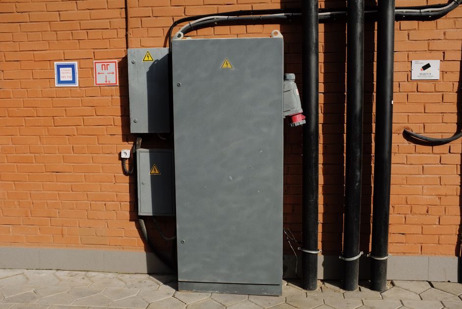
Environment, Enclosure, and Harmonics
Ambient temperature, altitude, dust, and corrosive atmosphere directly derate the drive: most industrial VFDs are rated to 40 °C / 1000 m a.s.l. Wall-mount (IP20/IP21) is standard inside a cabinet; IP54/NEMA 12 is the next step for washdown or dusty floors; IP66 is reserved for outdoor pump skids and food-grade washdown [S1].
Harmonics are the second environment gate. A 6-pulse rectifier produces a THDi of roughly 35–40% at full load; a 12-pulse or AFE front end drops that to 4–7%, which is what IEEE 519 and IEC 61000-3-12 require at the point of common coupling for larger units. For drives feeding hazardous-area motors, the cabinet must be ATEX/IECEx-certified and the motor must meet IEC 60079-0/60079-1 for the zone — the drive itself sits outside the classified area in most European and Chinese installations [S1].
Motor Pairing, Braking, and Cable Length
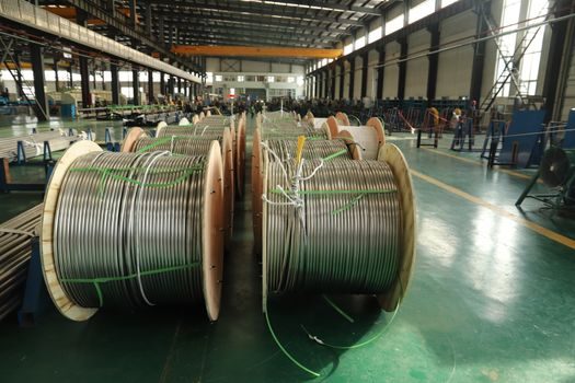
The default target for a modern VFD is a 3-phase AC induction motor, but pairing rules differ by motor type. Inverter-duty motors (NEMA MG1 Part 31) have reinforced winding insulation rated for the higher dV/dt at the drive output and are mandatory above ~15 kW or with cable runs over 50 m. A sine filter or dV/dt filter is added when the motor is older standard insulation, when the cable exceeds the manufacturer limit, or when the drive is feeding a long cable through a hazardous-area conduit [S1].
Braking is the next decision. For overhauling loads (downhill conveyors, winders, hoists) a regenerative line-side converter or a brake-chopper + brake-resistor is specified; for light-stop applications, DC injection or flux braking is enough. For selection consistency with adjacent drive train components, the Fluid Coupling vs Jaw Coupling spec-cut covers the mechanical half of the train and is worth reading alongside the electrical gates above.
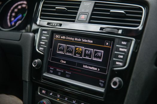
Communication, I/O, and Integration Stack
Fieldbus coverage is now table stakes: Modbus RTU/TCP is the default, PROFIBUS/PROFINET is the German and EU OEM default, EtherNet/IP and DeviceNet dominate the North American discrete market, and EtherCAT is the motion-bus default on servo drive and stepper drive lines. Wireless monitoring (Wi-Fi, cellular) and OPC UA over MQTT are the new integration layer for plant-level IIoT and energy dashboards [S1][S2].
I/O count, analog resolution (12-bit vs 16-bit), and the number of programmable digital inputs drive selection in retrofit work. For servo or coordinated motion lines, the motion controller cost gates article is a useful cross-reference because the same bus choice (EtherCAT vs PROFINET IRT) cascades into the VFD specification. For refrigeration and cold-storage applications in particular, the Danfoss application note specifies the additional gate of compressor-specific firmware, suction-pressure sensor input (4–20 mA or 0–10 V), and a low-ambient lubricant strategy [S1].
Comparison: Four Control Modes on Four Decision Criteria
The four common VFD control modes line up against four spec gates as follows. V/Hz scalar: low cost, poor low-speed torque, no encoder, no regeneration. Sensorless vector: mid cost, usable torque to ~0.5 Hz, no encoder, optional regen. Closed-loop vector: higher cost, full torque at zero speed, encoder required, regen via brake unit. DTC: high cost, fastest torque response (~25 µs), no encoder needed, regen possible. For pumps, fans, and HVAC the V/Hz or SVC tier is the right economic answer; for hoists, extruders, and crane drives closed-loop vector or DTC is the correct functional answer regardless of price [S1][S2].
What VFD Selection Is NOT For
A VFD is the wrong tool for sub-Hz positioning without an encoder; that is a servo drive job. It is also the wrong tool for single-phase 120 V household loads in North America, where the supply is single-phase and the motor is fractional-horsepower shaded-pole or PSC. And it is the wrong tool for very high-speed spindle work above the VFD switching-frequency limit (~500 Hz output on most industrial units) — that is a line-frequency furnace or high-frequency spindle drive category with a different topology entirely. The general rule: if the load is variable-torque or constant-torque AC induction in the 0.1–500 kW band, the VFD is correct; outside that envelope, re-evaluate the topology [S1][S2].
Trackable signals for the next planning window: a vendor releasing a 690 V low-voltage AFE drive in the ≤40 kW band (currently a gap), a fresh IEC 61800-9-1 energy-efficiency class II declaration on a high-volume mid-range line, and a confirmed lead-time movement on 11 kW 3-phase 220 V units in the China wholesale channel (current floor US$ 330–340 per piece) [S2][S4].