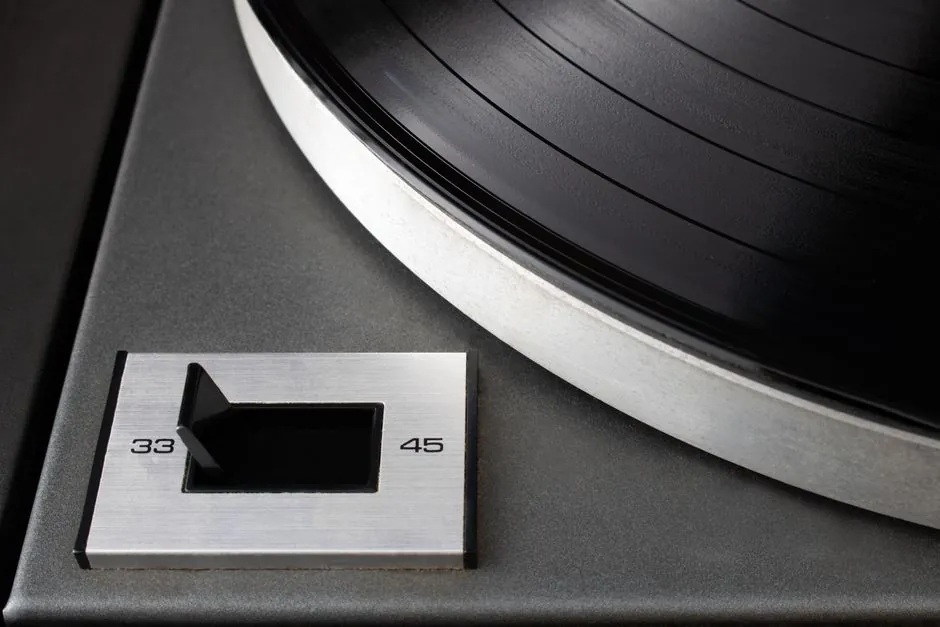
Two families dominate electronics-grade silicon steel: cold-rolled grain-oriented (CRGO) with roughly 3% Si for transformer cores, and cold-rolled non-oriented (CRNGO) at 2-3.5% Si for rotating machines and sensor diaphragms [S3].
Selection is driven by operating flux density (1.0-1.7 T for CRGO, 1.0-1.5 T for CRNGO), frequency band (50-400 Hz at power; 400 Hz and above for aerospace), and lamination thickness, not by trade name [S3].
CRGO vs CRNGO: Decision Criteria Across Four Axes
CRGO grades are produced with a sharp Goss texture {110}<001> and specified for unidirectional flux paths, so they outperform CRNGO by 30-50% on core loss at 1.5 T and 50 Hz, but lose that advantage as soon as flux rotates off the rolling direction [S2][S3]. CRNGO is randomly textured and is the correct pick for any application where flux rotates, including induction motor stator stacks and switched-mode power-supply chokes that carry AC components on top of DC bias [S3].
Lamination thickness is the second gate: 0.23 mm and 0.27 mm CRNGO grades are stocked for 400 Hz aerospace and EV traction inverters, while 0.30 mm and 0.35 mm remain the workhorse for 50/60 Hz industrial motors [S3]. The trade is a 10-15% core-loss penalty for every 0.05 mm of added thickness at 50 Hz, so a thicker grade is the right call only when the stamping tool cannot hold the thinner gauge without cracking the high-silicon edge.
Core-Loss Numbers That Drive the Pick
CRGO M4 (0.27 mm) is rated 1.6-1.7 W/kg at 1.5 T, 50 Hz, and high-permeability grades such as 30QG120 drop that figure toward 1.0-1.2 W/kg at the same excitation; CRNGO 50W470 sits closer to 4.7 W/kg at 1.5 T, 50 Hz, which is the price paid for isotropic behaviour [S3]. At 400 Hz the loss gap widens: a 0.20 mm CRNGO reaches 15-20 W/kg at 1.0 T, while thicker 0.35 mm grades run 25-35 W/kg at the same point, which is why aerospace designs refuse anything heavier than 0.23 mm [S3].
For pressure-sensor diaphragms and other low-flux electronics housings, the magnetic property is a side effect, not the goal. A silicon steel diaphragm in the 100 kPa to 100 MPa range exploits the alloy's elastic modulus and low magnetic signature to keep hysteresis below the sensor's resolution floor, with 4-20 mA transmitters cited as the dominant output [S1]. When magnetic permeability itself matters, the stainless steel alternative is magnetic but lower in saturation, while silicon carbide shows up in high-temperature pressure-sensor designs where silicon steel would drift.
Where Each Family Is Specified, and Where It Is Not
CRGO belongs in power and distribution transformers, audio output transformers, and any core carrying a strong unidirectional flux. CRNGO belongs in induction and synchronous motors, generators, and the magnetic circuit of chokes and small reactors. A common mistake is specifying CRNGO for a transformer to gain isotropic stamping behaviour; the core loss at 1.5 T will be 2-3x higher than a comparable CRGO core, and the magnetising current will rise with it. [S3]
For high-frequency electronics above 1 kHz, neither CRGO nor CRNGO is the right pick; amorphous ribbon (Metglas 2605SA1) and nanocrystalline 1K107 cut core loss by a factor of 3-5 at 10 kHz compared with 0.20 mm silicon steel, and ferrite becomes dominant above 50 kHz [S3]. Specifying CRNGO above its intended frequency band is one of the fastest ways to turn a motor into an oven.
Selection Workflow: From Frequency Sheet to Lamination Order
Step one: lock the operating flux density and frequency. If flux is unidirectional and frequency is 50/60 Hz, CRGO is the default; if flux rotates or the design runs at 400 Hz, CRNGO is the default. Step two: pick lamination thickness from the frequency band (0.35 mm for 50 Hz, 0.27 mm for 400 Hz, 0.20 mm for higher). Step three: read the core-loss curve for the candidate grade at the design B and f, and verify insulation coating class (C3, C5, or C6) matches the winding temperature class. [S3]
Step four: confirm the grade can be stamped at the required thickness without edge cracking. High-silicon (>=3%) CRNGO is brittle and needs a controlled clearance die; below 2% Si, stamping is easy but the loss budget suffers [S2]. Grades such as 50W470 are commonly stocked at 0.50 mm for cost-sensitive motor laminations, while 35W300 at 0.35 mm is the typical 400 Hz pick.
Standards, Coatings, and Procurement Signals

CRGO grades follow IEC 60404-8-7 class designations (M2, M3, M4, M5 by loss band), and CRNGO follows IEC 60404-8-4 (e.g. 50W470 means 0.50 mm nominal, 4.7 W/kg max loss at 1.5 T, 50 Hz). Coatings are referenced to IEC 60404-1-1 for insulation class and to ASTM A976 for coating weight. Procurement listings out of China show both 0.23 mm and 0.35 mm CRNGO coils, plus 0.27 mm CRGO M4, as in-stock grades with 4-20 mA pressure-sensor reference designs built on the same family [S1][S3].
For tool-steel comparison points on stamping dies that cut silicon-steel laminations, the grade map in tool and die steel selection for energy equipment lines up D2 and S7 against the wear and impact loads these tools see, while structural comparison points on cast iron selection for aerospace sit one level upstream of the steel lamination decision.
Trackable signals for the next quarter: published loss curves for 0.20 mm CRNGO at 1.0 T, 400 Hz from major mills; stocking of 0.23 mm high-permeability CRGO for distribution transformers; and the 4-20 mA pressure-sensor family (-100 kPa to 100 MPa) that uses silicon steel diaphragms as the magnetic-shunt element [S1][S3].