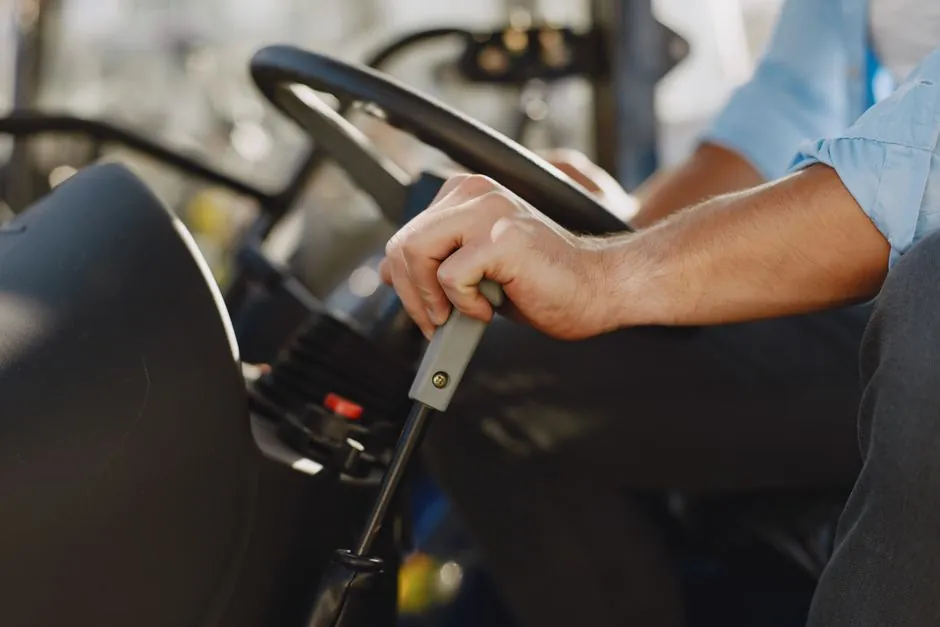
Every modern skid steer runs two independent final drives, one per side, each combining a hydraulic travel motor with a speed-reducing gearbox that turns pump flow into wheel torque [S1][S2].
The architecture is a direct consequence of skid steering: wheels have fixed orientation, so direction is changed by driving the left and right sides at different speeds, or in opposite directions during a zero-radius turn [S1][S4]. The two side drives almost never see identical loads during a maneuver, which sets the layout and duty cycle of every component downstream of the engine.
Two Halves, Two Sides: Hydraulic Motor Plus Gearbox
A skid steer final drive is mechanically split into a hydraulic travel motor and a reduction gearbox, with the motor on the side where the hydraulic hoses connect [S5][S6]. The motor converts pump flow into rotation; the gearbox then trades that rotation for torque at the wheel hub through planetary gear sets, and in many wheeled machines through a chain-and-sprocket stage as well [S1][S2][S5].
Final drives, drive motors, and travel motors are the listed service-replacement categories in the parts market for these machines, alongside hydraulic pumps, swing drives, and track frames on compact track loaders [S3][S7]. On a chain-driven wheeled skid steer, each motor carries a sprocket that drives both front and rear wheels through a heavy-duty chain running in a sealed oil bath, keeping the two wheels on one side locked to the same speed [S1].
Component Breakdown: What Sits Inside the Final Drive
The standard internal stack is hydraulic motor, then a planetary gear reduction stage, then an output coupling to the wheel hub or sprocket [S2][S5]. On chain-driven wheeled layouts, a short shaft with seals links the gearbox output sprocket to the hub that mounts the wheel, while the chain itself sits in an oil bath that lubricates both the chain and the sprockets [S1].
Track-frame compact machines drop the chain stage and use the planetary reduction to drive a sprocket on the track frame directly [S5]. Common wear items across both layouts are seal leaks, worn gears, and overheating under sustained maneuvering load, the three failure modes that drive most rebuilds [S2]. The motor half fails first in many cases; if one side's travel motor goes down, the machine physically can only go in circles, which is why preventive rebuild windows are usually set against motor hours, not machine hours [S1].
Why the Layout Differs From Crawler Travel Drives
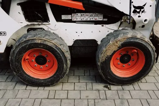
Skid steer travel drives must tolerate high torque at low speed, rapid direction changes, heat from frequent maneuvering, two-speed shifting, and a compact installation envelope inside the drive frame [S4]. Crawler machines on long straight runs sit near a single steady load point; skid steers cycle through low-speed high-torque, near-zero, and counter-rotation states in a single turn [S4].
Ground surface amplifies the effect. On loose soil the track or wheel can slip sideways during a turn, easing load on the drive; on concrete or asphalt the same turn generates strong scrub resistance that the final drive has to overcome as additional torque demand [S4]. A loader working demolition on hard ground and an equivalent-weight unit on soft landscaping can therefore see very different drive-side loads even with identical operating weights [S4].
Closed-Loop Hydrostatics and the Two-Speed Travel Option
Skid steer travel systems almost universally use closed-loop hydrostatic circuits, where the variable pump and the travel motor form a sealed circulation path, because that topology supports the constant accelerate-decelerate-reverse cycle of skid work [S4]. Changing pump flow changes motor speed; reversing flow reverses direction, and the motor's stable low-speed behaviour is what makes controlled zero-radius turns possible [S1][S4].
Two-speed travel is an added layer on top of that base circuit, with a high range for roading between sites and a low range for the high-torque low-speed work that defines most attachments. The shift is handled inside or adjacent to the final drive, and the gearbox must accept both ratios without losing the parking-brake holding torque that operators depend on when working on slopes [S4]. Comparisons of radial versus vertical lift path designs, which sit on the same machine platform, show how the same drive package is asked to deliver very different tractive loads depending on the work cycle, a useful reference point in the skid steer lift path decision matrix.
Selection Criteria and a Side-by-Side Layout Comparison
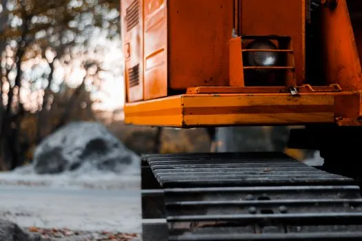
The four decision criteria below are the ones a parts or rebuild specifier actually has to weigh when choosing between a chain-and-sprocket wheeled final drive, a hub-drive wheeled final drive, and a track-frame final drive for a compact track loader [S1][S2][S4][S5].
For OEM-style specification of the whole machine, see the skid steer loader reference page, and for broader drivetrain context across earthmoving equipment the construction machinery and equipment entry covers the family. Selection beyond the drive itself, including lift-arm geometry and auxiliary flows, is laid out in the skid steer attachments spec breakdown for high-pressure auxiliary work.
Failure Modes, Maintenance Windows, and Rebuild Boundaries
The three dominant final-drive failure modes are leaking seals, worn or chipped gear teeth, and motor overheating from sustained low-speed high-torque maneuvering [S2]. Contamination is the upstream cause of most of these: dust ingestion through failed seals, infrequent oil changes that break down the chain-case lubricant, and continuous counter-rotation work that cooks the motor case [S2].
Maintenance practice is therefore seal inspection, oil-level and oil-condition checks at fixed motor-hour intervals, and aural monitoring for the first signs of planetary gear wear [S2]. A useful sanity check on the drivetrain's thermal state is the loop pressure and return-line temperature at the travel motor, which can be read with a gauge or differential pressure transmitter tied into the diagnostic port. Rebuild or replacement becomes economic once any two of seal leak, gear noise, and heat-soak are present together; replacing only the motor half while keeping the planetary set is the common cost-control move on chain-driven layouts where the gearbox typically outlasts the motor by one or two rebuild cycles [S1][S2].
Sourcing, Warranty, and Trackable Signals
The aftermarket for skid steer final drives covers both OEM and aftermarket units, with stock lines that include final drives, hydraulic pumps, swing motors, and travel gearboxes across brands such as Bobcat, Caterpillar, Case, John Deere, New Holland, Gehl, Kubota, ASV, and Takeuchi [S3]. Bench-tested assemblies with a 12 to 24 month warranty, plus a separate reconditioned and rebuild-kit tier, are the standard commercial offering in this category [S3].
Two trackable signals for the next quarter are the rate of closed-loop pump-and-motor paired remanufacturing programs offered by major OEM dealers, and any second-source planetary gear set qualified for two-speed travel applications; either will shift the rebuild-economics calculation for fleet operators running mixed-brand skid steer and compact track loader fleets.