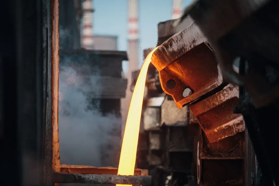
Steel-mill slewing ring bearings sit in a different operating envelope than crane or wind-turbine units: continuous high moment load, scale and water contamination, ambient temperatures often cycling 200–400 °C around the bearing seat, and slow rotation under near-static load [S1][S5].
Practical selections land in the 1,500–4,500 mm bore range for ladle turrets, slag-skimmer turntables, and continuous-caster segment supports, with three-row roller or crossed-roller designs carrying combined axial loads typically above 2,000 kN and continuous tilting moments [S1][S3]. Single-row four-point contact ball units still dominate stacker-reclaimer and basic-oxygen-furnace (BOF) turntable duties where rotation speed stays under 2 rpm and the moment is moderate.
Why Steel-Mill Duty Is Its Own Selection Problem
Mill slewing rings rarely fail from a single shock load; they fail from the combination of sustained moment, thermal cycling at the support, and abrasive ingress from iron oxide, lime dust, and cooling water [S5][S7]. A unit that would last 30 years on a harbor crane will typically be derated 30–50% in service life once installed in a caster or ladle turret.
For that reason, the design process has to start with three mill-specific inputs: the maximum combined load case (Fa, Fr, M) at the worst casting sequence, the ambient-plus-frictional temperature at the bearing periphery, and the contamination class (scale, slag spatter, mill water, basic-oxygen dust). Skipping any one of these collapses the life calculation to guesswork, per the standard calculation chain described in ISO 76 (static) and ISO 281 (dynamic) [S2].
The Main Slewing-Ring Types and Where They Fit in a Mill
Single-row four-point contact ball bearings are the lightest, cheapest option, with raceway hardness HRC 55–62 on 42CrMo4 rings, and they handle simultaneous axial, radial, and moderate moment loads in one raceway [S3][S6]. They are the default for stacker-reclaimer slews, BOF turntables, and coke-car dumper turrets where rotation stays under 2 rpm and moment peaks are bounded.
Double-row ball slewing rings add a second raceway, roughly doubling moment capacity at the same diameter, and are used where designers want the simpler ball-bearing geometry but need higher tilting stiffness. Crossed-roller slewing rings replace balls with cylindrical rollers set at 90°, giving line contact instead of point contact, and roughly 2–3× the moment capacity of a single-row ball of the same diameter, at the cost of higher friction and tighter mounting tolerance [S1][S6].
Three-row roller slewing rings add a third row of rollers dedicated to the moment load, and are the standard for the heaviest mill applications: ladle turrets, tundish cars, and continuous-caster segment turntables, where combined axial load regularly exceeds 2,000 kN and the bearing is essentially statically loaded through much of the casting sequence [S1][S3][S6]. For the inner ring and outer ring material itself, 42CrMo4 (DIN equivalent of AISI 4140) normalized and tempered, with induction-hardened raceways, is the dominant specification across manufacturers [S3].
Material, Hardness, and Heat: What Has to Be on the Datasheet

Raceway hardness must be specified as induction-hardened HRC 55–62 with a case depth of typically 3–6 mm on 42CrMo4 (or 40Cr / 50Mn) rings, normalized and tempered to a core tensile strength in the 900–1,100 MPa range [S3]. Below HRC 55 the rolling-contact fatigue life drops sharply; above HRC 62 the risk of raceway spalling under the high moment load increases.
For temperature, the bearing has to be selected so that the operating temperature at the raceway stays within the lubricant window. Mill slewing rings typically run 60–120 °C at the bearing, with short transients to 150 °C during ladle-furnace swings; standard greases rated to 120 °C continuous, 150 °C peak, are the usual spec, with synthetic polyurea or complex-calcium greases preferred for their water resistance [S2][S5]. Above 150 °C continuous, the polymer cages have to be replaced by brass or steel.
Sealing is the second life-defining decision. Mill environments throw iron-oxide scale, lime, and water at the seal lips; the standard spec is a double-lip nitrile rubber seal on both faces, with a grease-purge channel between lips, and on ladle-turret units an additional metallic scraper ring outboard of the rubber lip [S2][S7]. This setup is essentially a slewing bearing sealing stack, not a single lip; skimping on the second lip is the most common cause of premature grease loss.
Gearing, Mounting, and the Drive Train Side
About two-thirds of mill slewing rings are driven, typically by a single or twin pinion meshing with external gear teeth cut into one ring, or internal teeth for enclosed drives where contamination protection matters [S2][S3]. External gears are easier to inspect and re-shim, internal gears give a smaller envelope and better protection, but require the pinion to be mounted through the ring, which complicates maintenance.
Gear module for mill duty usually lands in m = 8 to m = 16 for the 1,500–4,500 mm diameter range, with surface-hardened teeth (HRC 50–55) on the same 42CrMo4 ring. Pinion life is the maintenance bottleneck; it is worth overspecifying the pinion hardness by 2–4 HRC above the ring, and using a 20CrMnTi case-hardened pinion, so the wearing element is the cheaper part. For mill slewing drives the integrated slewing drive package (bearing, planetary gearbox, motor adapter, brake) is increasingly specified for new ladle turrets because it removes the alignment risk between separate components, but it locks the plant into the drive manufacturer's spares list.
Standards, Calculation Inputs, and What Buyers Should Verify
The three standards that always show up in a mill slewing-ring datasheet are ISO 76 (static load rating), ISO 281 (dynamic load rating and reference rating life), and ISO 492 (dimensional and running accuracy tolerances) [S2]. For gear integration, ISO 1328 covers the gear accuracy class, and FEM 1.001 applies when the same slewing ring is also acting as a structural element in a crane-mounted turret. Material certificates have to be traceable to the actual heat, and heat-treatment charts (through-hardness curve, case depth) are routinely requested at RFQ stage for mill orders [S4][S5].
For RFQ discipline, the buyer should send the maximum combined load case (Fa, Fr, M), the rotation speed and duty cycle (hours/day, cycles/hour, reversal frequency), the ambient and bearing-periphery temperature profile across a full casting sequence, the contamination description (scale, slag, water, dust), and the mounting structure stiffness. Any manufacturer that quotes on catalog static-load numbers alone, without asking for the duty cycle, should be deprioritised; the standard supplier landscape, including Rothe Erde, SKF, IMO, and a tier of qualified Chinese mills, separates itself precisely on engineering depth at this step [S4].
Failure Modes and the Maintenance Signals Worth Tracking
The three dominant in-service failure modes for mill slewing rings are rolling-contact fatigue (raceway spalling), abrasive wear accelerated by seal failure, and white-etching cracking or brinelling from impact events during ladle landings [S5][S7]. Each of these produces a different signal: spalling shows up as broadband vibration in the 1–5 kHz band on the slew drive housing, seal failure shows up as grease leaking past the lower lip and dropping grease analysis iron-content readings, and brinelling shows up as a sudden increase in starting torque on the next rotation.
Routine grease sampling (every 500 hours or once per casting sequence, whichever is shorter) for particle count, iron content, and water content catches seal degradation before the raceway is damaged. Laser alignment checks between the pinion and the slewing-ring gear teeth every 12 months, and torque audits on the mounting bolts (typical M36 grade 10.9 preloaded to roughly 70% of yield) every 6 months, are the standard preventive tasks; plants that run these on a real calendar rather than after a failure typically see slewing-ring life on the slewing ring bearing side extend past 15 years even on continuous-caster duty. The reference ball bearing data sheets for the equivalent rolling-element fatigue curves are useful when a mill engineer wants to sanity-check a vendor's L10 life claim against ISO 281 inputs.
Trackable next signals for steel-mill slewing-ring buyers: vendor-by-vendor lead times have stretched into the 16–28 week band for the 2,000–4,500 mm class in 2026, so any mill planning a caster or turret retrofit should be placing the bearing RFQ at least 9 months before the planned outage. Watch also for the wider mill-slewing picture, including cement-plant and harbor-crane references, in the related Slewing Ring Bearing Selection for Cement Plants: Load, Seal, Gear Spec Map guide, which uses the same selection framework against a different contamination and temperature profile.