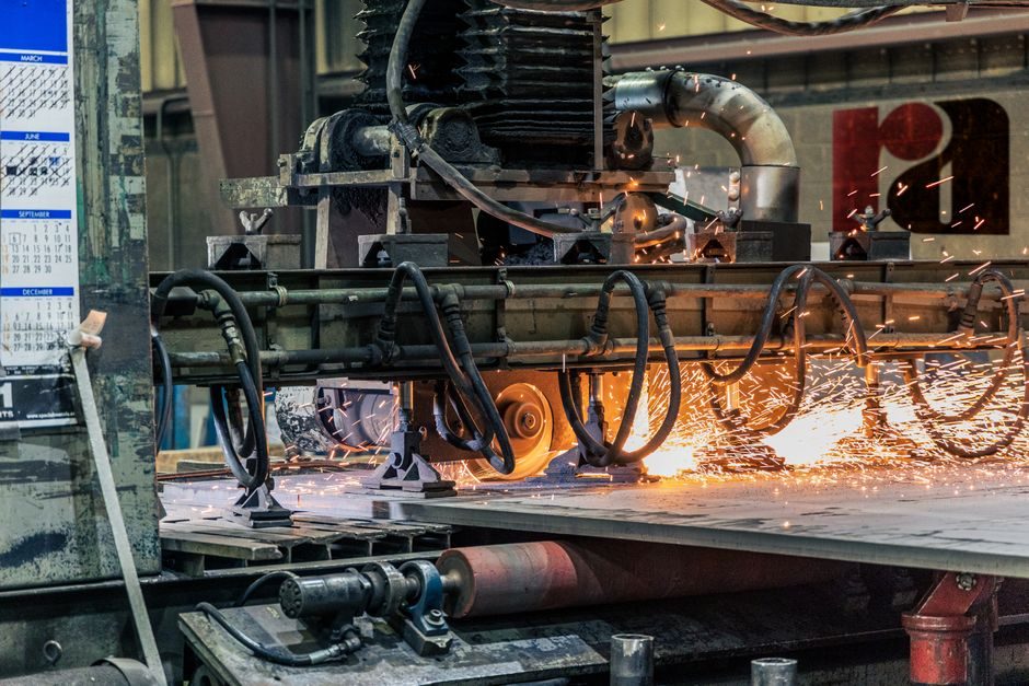
A solar-grade front sheet is a low-iron soda-lime flat glass with 3.2 mm nominal thickness, 120 MPa temper strength, and an AM1.5 solar transmission above 91% after AR coating, supplied as either patterned (c-Si front cover) or float (TCO substrate and back glass) [S1][S5].
The line runs raw silica, soda ash, and limestone through a >1560 °C furnace, a tin bath or patterned roller, an annealing lehr, an offline tempering and AR-coating stage, and finally cutting to the 3.2 mm / 4.0 mm panel sizes the c-Si and thin-film lines consume [S5][S7].
Raw Batch and Iron Control
The standard solar-glass batch is high-purity silica sand, soda ash, and limestone, with low-iron sand and low-iron limestone substituted where available because ferrous and ferric iron in the silicate network absorbs strongly between 300 and 1,100 nm [S1].
Iron control is the single biggest lever on transmission: a 1 ppm Fe₂O₃ drop in the melt typically buys back 0.3-0.5 percentage points of AM1.5 transmittance on 3.2 mm glass, which is why pattern and float lines targeting solar output run higher refining temperatures and stricter cullet sorting than container-glass furnaces [S1]. Base-line commercial (non-solar) glass already loses 16.3% of incoming solar energy, with reflection and iron absorption each contributing roughly half of that loss [S1].
Float vs Patterned Forming
Two forming routes dominate the solar-glass market: the float bath, where molten glass spreads over a tin pool and is pulled off as a fire-polished ribbon, and the patterned roll, where an engraved metal roller imprints a prismatic surface into the still-plastic ribbon [S1].
Patterned glass is the default front cover for crystalline-silicon modules because the micro-pyramid pattern scatters incident light into the encapsulated cell, lifting effective short-circuit current by 2-3% relative to smooth float at the same AR coating; float glass, with its lower surface roughness, is the chosen substrate and back sheet for thin-film modules and for BIPV laminates where optical clarity matters more than light-trapping [S1]. For related process-line context on glass-based photovoltaics, see optical glass forming fundamentals.
Annealing, Tempering, and Strength Stack-Up
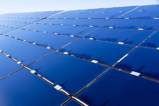
After forming, the ribbon enters an annealing lehr that stress-relieves the glass at around 620 °C; for solar applications the lehr output is then routed to a tempering line that re-heats the cut sheet to ~620 °C and quenches it with high-velocity air [S1].
Quenching induces a compressive skin layer that roughly quadruples the load-bearing capacity of the sheet: annealed soda-lime glass tests at ~45 MPa tensile strength, toughened stock at ~70 MPa, and fully tempered solar-grade stock at ~120 MPa [S1]. That 120 MPa rating is what lets a 3.2 mm sheet survive 5,400 Pa wind/snow loads and the 25 mm ice-ball impact test (IEC 61215) without crack propagation, and it is also what dictates the cut-to-temper cycle time on the line: a 3.2 mm sheet needs roughly 8-12 seconds of quench to lock in the residual-stress profile [S1].
AR Coatings and Surface Engineering
Anti-reflective coatings are typically single- or double-layer porous SiO₂ deposited by sol-gel dip or by APCVD at the exit of the tempering line, tuned to a quarter-wave optical thickness at 550-600 nm to suppress the Fresnel reflection that otherwise costs 3-4 percentage points per air-glass interface [S1][S7].
Beyond AR, the surface stack frequently adds anti-soiling (TiO₂ photocatalyst) and self-cleaning (hydrophobic fluorosilane) layers, and for thin-film modules a transparent conductive oxide (TCO) is deposited on the float side that faces the cell; TCO choice drives most of the substrate-vs-superstrate architecture decision in CdTe and CIGS lines [S1][S7]. Anti-soiling performance is one of the few places where end users will pay a 5-8% premium over commodity AR glass, and it is also the layer most sensitive to high-humidity storage, so stacking order (AR on the air side, never on the EVA side) is non-negotiable [S7].
Cutting, Edge Work, and Lamination Feedstock
Tempered sheets are cut to size before tempering on a standard float-line CNC cutting table; once tempered, the sheets cannot be re-cut except by abrasive water-jet, which is why solar lines run the geometry cutter upstream of the quench [S1].
Standard cut sizes cluster around 1,600 × 1,000 mm and 1,200 × 600 mm to match the cell-string lay-ups used by mainstream c-Si module lines; nominal thicknesses in the catalog are 2.0 mm, 3.2 mm, and 4.0 mm, with 3.2 mm holding roughly two-thirds of unit volume for rooftop and utility-scale modules [S2]. Density is fixed at about 2,500 kg/m³, so a 3.2 mm sheet weighs 8.0 kg/m² and accounts for roughly 67% of total weight in a c-Si module and 96% in a thin-film module (two 3 mm sheets laminated) [S1][S2].
Spec Bands and Decision Matrix
Solar glass is specified on four axes: transmission, mechanical strength, thermal stability, and form (pattern vs float); the table below lines them up against the two dominant process routes [S1][S3].
Pattern-tempered is the default for c-Si front covers because the embossed surface adds light-trapping; float-tempered dominates thin-film and BIPV because the smooth face accepts TCO deposition and the back-side lamination without optical scatter [S1][S3]. For BIPV, CdTe on glass (Polysolar PS-CT, 12% / 118 Wp/m² efficiency, opaque to 80% light transmission) and mono c-Si on glass (PS-MC-ST, 20% / 210 Wp/m² at 10% standard transmission) are the two commercial reference points that define the BIPV glass spec envelope [S3].
Failure Modes and Sourcing Reality
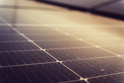
Field failures on solar glass break into four patterns: iron-driven transmission loss (low-iron batch drift), temper stress relaxation at sustained >90 °C rooftop temperatures, AR-coating delamination under PID bias, and edge-chip-initiated fracture during robotic handling at the module line [S1][S7].
Chinese manufacturers such as Hangzhou Dongke New Energy Technology Co., Ltd produce solar tempered glass in standard module-cover thicknesses including 3.2 mm and 4.0 mm, along with low-iron and TCO-coated glass variants for photovoltaic and thin-film applications. Trackable signals over the next two quarters: (1) any post-tempering AR-coating in-line integration that removes the offline coating step, and (2) tighter EN 1288-3 edge-strength reporting as 600 W+ bifacial modules push 4.0 mm pattern-tempered into mainstream spec [S5][S6].
For component-level specifications, see additive manufacturing material, and multifunction process calibrator.