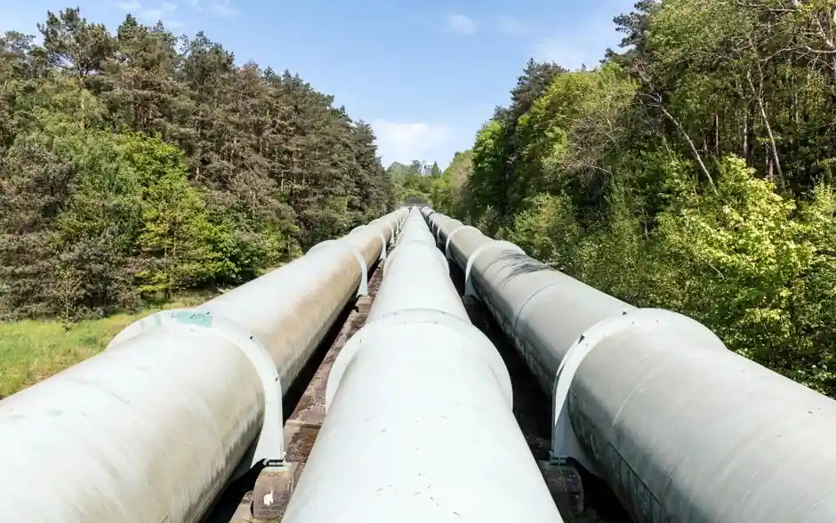
A double disc pack coupling, sometimes called a spacer disc coupling, absorbs parallel shaft offset by splitting the misalignment across two flex planes: each disc pack contributes a small angular pivot, and the rigid spacer between them converts those pivots into lateral travel at the driven shaft. The geometric rule is straight, the parallel offset capacity rises roughly in proportion to the center-to-center distance between the two disc packs [S1][S5].
Single disc pack designs cannot absorb parallel offset on their own, because one flex plane has no second pivot to close the parallelogram, so a parallel-offset application forces the engineer to either accept a self-aligning bearing on the second shaft or move up to a double disc pack (or floating-shaft) architecture [S1][S3][S4].
Why a Second Disc Pack Is What Unlocks Parallel Offset
A single disc pack is rigid in shear, so it can pivot to absorb angular misalignment but cannot translate laterally to absorb parallel offset unless a second flex plane is provided to complete the geometry [S5]. A self-aligning bearing on the second shaft can substitute for that second flex plane, but in practice the second flex plane is almost always built as a second disc pack, with a tubular spacer between the two packs carrying the torque across the gap [S1][S3].
This two-flex-plane architecture is what makes a disc coupling the go-to choice on turbomachinery trains where API 671 alignment tolerances cannot be guaranteed over a 5 to 20 year service life, and it is the same architecture that allows floating-shaft couplings to span long distances between a motor and a remotely mounted pump or gearbox [S2][S4].
The Geometry: Offset ≈ 2 × Spacer Length × sin(Angular Pivot)
For small angles, the parallel offset that a double disc pack can absorb is approximately equal to twice the spacer length multiplied by the sine of the per-pack angular pivot, which is why catalogs publish the relationship as offset budget growing linearly with the distance between disc packs at a fixed angular rating [S5]. Designers can therefore trade a longer spacer for more parallel capacity, but only up to the per-pack angular limit, beyond which the disc pack fatigue life and bending stress become the binding constraint [S1][S5].
The angular rating itself is set by the disc pack geometry, by stack thickness (commonly 4 to 12 shims per pack, each 0.4 to 1.0 mm thick) and by the bolt circle diameter, so a coupling cannot be made "softer" in offset simply by stretching the spacer, the per-pack angle cap remains fixed and the disc pack is what fails first if the calculation is abused [S1][S5].
Real Catalog Numbers From Major Disc Coupling Lines
SKF's W-series disc couplings list parallel offset as a stated catalog parameter for the W4 (4-bolt single), W6 (6-bolt double) and W8 (8-bolt double) families, with the offset budget increasing as the spacer between disc packs grows; the same catalog also quotes a high-speed balancing capability above 50 m/s for floating-shaft disc configurations [S4]. Lovejoy's disc coupling catalog (SU-6, SX-6, SX-8, SXC-6, SXCS-6, SXCST-6, DI-6, DI-8 and the DIR/DILR floating-shaft series) calls out two flex planes as the feature that lets the coupling accept parallel, angular, and axial misalignment within its rated limits [S2].
Wood's flexible coupling catalog (TB-Wood, sizes 1 through 5-1/2) ties horsepower, torque, and parallel misalignment capacity to a per-mesh angular limit of 1.5 degrees per gear mesh in the flexing element, a useful reminder that published parallel offset numbers are only valid when the corresponding angular rating is also respected at each flex plane [S6].
Where the Long-Spacer Architecture Shows Up in Practice
Long-spacer disc couplings are common in pump rooms where a motor and a pump sit on separate baseplates and thermal growth of the skid will move the shafts laterally by several millimetres over the operating cycle, in cooling-tower fan drives where the input shaft and gearbox are physically separated, and in API 671 turbocompressor trains where the spacer often carries a spacer tube long enough to remove the spacer and slide the driver out for maintenance without disturbing the driven machine [S2][S4].
For small precision axes, the same engineering logic shows up in miniature form: a jaw coupling and a beam coupling trade off misalignment, stiffness, and backlash in much the same way a disc coupling does, and the relevant selection decision for stepper and encoder feedback shafts is laid out in Miniature Jaw Couplings for Encoder Feedback Shafts: Spec-Level Selection.
Limits and Failure Modes of the Spacer-Length Trick
Lengthening the spacer buys parallel offset but costs you three things at once: a lower first lateral bending natural frequency, a higher centrifugal moment on the spacer tube, and a larger reaction load on the bearings if the spacer is misjudged. SKF's coupling catalog explicitly notes high-speed balancing above 50 m/s as a feature of floating-shaft disc configurations, which is only achievable when the spacer is dynamically balanced as a rotor in its own right [S4].
The other failure mode is the one designers forget: a longer spacer raises the lever arm between flex planes, so any residual angular misalignment that would be harmless in a short coupling becomes amplified lateral motion at the second disc pack, and that is why floating-shaft and long-spacer API 671 builds usually demand a tighter installed alignment tolerance than a standard close-coupled disc coupling [S1][S2]. The practical fix is to enter the spacer length as an explicit input in the misalignment budget, not as an afterthought once the disc pack has already been chosen.
Comparison: Short, Standard, and Floating-Shaft Disc Configurations
Side by side on the three criteria that matter most when the spacer is being sized, a close-coupled double disc coupling, a standard spacer disc coupling, and a floating-shaft disc coupling line up roughly as follows. Parallel offset capacity: close-coupled is the smallest, standard spacer is the OEM-rated middle value, floating-shaft is the largest because the spacer length is maximized. First lateral bending frequency: close-coupled is highest, standard is intermediate, floating-shaft is the lowest and is the one that most often dictates a balance grade above AGMA 9 or a speed limit. Maintenance access: close-coupled is the worst (driver must be moved for service), standard is better, and floating-shaft is the best because the spacer tube can be removed to slide the driver out without disturbing the driven machine [S2][S4].
For a general introduction to how the same trade-off shows up in smaller, lower-torque coupling families, see Miniature Jaw vs Beam Coupling for Small Stepper Axes, which applies the same parallel-versus-angular capacity logic at a much smaller scale.
Spec-Level Takeaways for Engineers Sizing the Spacer
Enter the spacer length as a first-class input, not a derived one, in the misalignment worksheet, and tie it directly to the per-pack angular limit the disc pack manufacturer publishes, because the offset budget is just the projection of that per-pack angle across the spacer [S1][S5]. For a shaft coupling in a long-spacer configuration, verify the first lateral bending frequency of the spacer against the running speed, request a balance certificate tied to ISO 1940 G2.5 or better for any coupling that will run above roughly 30 m/s peripheral speed, and confirm the bearing-reaction load at the worst-case installed offset before the order is released [S2][S4][S6].
Trackable next signals: the SKF W-series and Lovejoy DI/SX disc catalogs remain the public reference points for offset-versus-spacer curves, and any new release of a G2.5-balanced floating-shaft disc catalog page in Q4 2026 would be worth a side-by-side review against those two lines.