
Spiral duct diameter is selected from two inputs, airflow in CFM and a target air velocity in FPM, then solved through the round-duct area formula D = sqrt(4 x CFM / (pi x V)); for a 2,000 CFM residential supply trunk at 1,500 FPM the calculated inside diameter is 15.6 in, while a 1,000 CFM run at 1,000 FPM sizes to a 13.5 in round equivalent [S2].
Standard spiral stock covers 80 mm to 900 mm diameter with a range of intermediate sizes to fit standard fittings [S1]. Designers set the friction-loss target first (0.1 in. w.c. per 100 ft of equivalent length is the residential baseline), then pick a velocity class, then read the chart, rather than the reverse.
The core equation and what each term actually does
The round-duct area equation A = Q / V, where Q is CFM and V is velocity in FPM, gives the required cross-section in square feet; the equivalent diameter follows from D = sqrt(4A / pi) [S2][S6]. For a 7,500 CFM industrial supply at 4,000 FPM the math yields a 30 in round duct, which is the textbook reference case used to compare round, rectangular, and equivalent-diameter conversions [S8]. CaptiveAire's online tool publishes the same primary equation and lets you solve for D directly from CFM and a target velocity [S6].
Two practical corrections sit on top of the formula. First, the CFM number must already exist; it is the output of a Manual J load calculation, not a guess, and ACCA Manual D then turns that CFM into duct sizes using an approved friction rate [S4]. Second, every fitting adds equivalent length: a single square-throat 90 degree elbow on a 16 in to 21 in duct adds 75 ft EL, versus 15 ft for a radius-throat elbow of the same size, so the velocity check has to be repeated after fittings are summed [S4].
Velocity targets by application: residential, commercial, industrial
Residential supply trunks are normally held to 600 to 900 FPM to keep noise and pressure loss in check, and a 20 in smooth-wall metal duct at that velocity class carries about 2,000 CFM [S3][S5]. Forum field data from a 2,000 CFM blower install shows the same 20 in round as the practical minimum for a smooth-wall run, with a 18 in trunk stepping down toward individual 8 in to 12 in branch takeoffs [S3]. Going larger than the chart value wastes material; going smaller pushes velocity past the acoustic limit and inflates friction loss.
Commercial systems typically run supply mains at 1,500 to 2,500 FPM, and industrial dust-collection and process-duct runs can push 3,500 to 4,500 FPM because acoustic comfort is not the constraint [S2][S8]. The same CFM produces very different diameters at each velocity class: 1,000 CFM at 1,000 FPM gives a 13.5 in duct, but 1,000 CFM at 2,500 FPM shrinks to about 8.6 in, a 60 percent reduction in cross-sectional area [S2]. Sizing-by-velocity is the method, but sizing-by-friction-loss (the ACCA Manual D / ASHRAE method) is the override that selects the velocity for you [S4][S5].
Spiral versus smooth-wall: the field correction that breaks textbook math
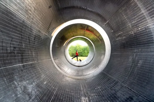
Spiral seam duct has a higher effective roughness than smooth-wall sheet metal, so the same nominal diameter delivers less CFM for the same friction rate; a 20 in spiral at standard residential friction loss moves about 1,800 CFM versus 2,000 CFM in a smooth-wall 20 in of the same gauge [S3][S4]. When a chart entry is borderline, most specifiers round up one nominal diameter, or about 2 in on a 20 in trunk, to keep the velocity in band [S5]. The Southwark Metal Duct School reference table is published at a friction rate of 0.09 to 0.10 in. w.c. per 100 ft equivalent length, which is the convention ACCA Manual D uses for residential rigid metal [S4].
Flex duct is the other correction that catches people. A corrugated flexible run carries far less air per inch of diameter than spiral or smooth-wall, so most guides specify upsizing by 1 to 2 in over the rigid equivalent [S5]. Return ducts are sized to the same friction rate as supply but usually one nominal size larger because return grilles and filter racks add their own pressure drop; undersized returns are a top-three cause of frozen coils and overheated heat exchangers in the field [S5].
Side-by-side sizing comparison at 2,000 CFM
The same 2,000 CFM target produces four meaningfully different answers depending on method, and the table is the cleanest way to see why method choice matters more than the calculator you run it through [S2][S4][S5].
Method 1, sizing by velocity at 1,500 FPM: round duct 15.6 in, area 1.33 ft squared [S2]. Method 2, sizing by velocity at 900 FPM (residential quiet-supply ceiling): round duct 20 in, area about 2.18 ft squared, rectangular equivalent 26 in x 10 in at the same friction rate [S4][S5]. Method 3, sizing by friction rate using the Southwark table at 0.1 in w.c. per 100 ft: round duct 18 in, with a 26 in x 10 in rectangular alternative at 0.1 in w.c. per 100 ft equivalent length [S4]. Method 4, spiral-duct field correction: round out to 20 in nominal to recover the 1,800 CFM that 18 in spiral actually delivers at the same friction rate [S3]. The decision criterion is the velocity limit set by the application, not the math.
Limits, failure modes, and where the equation breaks

The A = Q / V approach is wrong the moment you forget the equivalent-length correction, because real ducts have fittings, not straight pipe. A residential 90 degree square-throat elbow on a 14 in duct adds 40 ft EL, and the same fitting on a 28 in to 33 in duct adds 125 ft EL, which can shift your operating point by a full velocity class if you do not include it [S4]. The Southwark adjustment table is built exactly for that: at 75 ft of total effective length and 0.10 design friction rate, the multiplier is 0.13, meaning you need to upsize diameters from what a straight-pipe calculation would give [S4].
Second failure mode: stating CFM without a Manual J load calc. Forum respondents on a 125,000 BTU furnace with a 2,000 CFM blower explicitly redirect the original poster to a Manual J plus Manual D before picking duct sizes, because a wrong load calc flows straight into wrong CFM and therefore wrong diameter [S3]. Third failure mode: ignoring altitude. The 4,000 FPM target at 5,000 ft elevation is not the same mass flow as 4,000 FPM at sea level, and air-density corrections belong in industrial and high-altitude designs even though residential charts usually skip them [S2].
Standards, sourcing, and what to verify before ordering
Residential rigid metal sizing follows ACCA Manual D with the ASHRAE-aligned friction rate of 0.1 in w.c. per 100 ft of equivalent length as the standard baseline, and every CFM input should be traceable back to a Manual J load calculation [S4][S5]. Portlandia Electric Supply's 2026 sizing reference reiterates that even small sizing errors can drive HVAC energy cost up by 20 to 30 percent, so the chart is a verification step, not a shortcut around the load calc [S5]. For high-pressure industrial runs, ASHRAE and SMACNA guides govern gauge, seam class, and reinforcement, which is why the same 20 in duct can be ordered in different gauges depending on static pressure class.
Spiral duct standard stock from 80 mm to 900 mm covers most residential, light-commercial, and dust-collection jobs out of catalog [S1]. If a sizing problem keeps returning diameters outside that range, the inputs are usually wrong: the CFM is too high, the velocity limit is too aggressive, or the equivalent length has been ignored. Re-run with a measured CFM and a realistic friction rate before ordering nonstandard diameters, since spiral fittings, especially wiring-duct style trunks and rectangular-to-round transitions, are stocked in standard increments and odd sizes add lead time. For applications where the duct carries air to or from other process equipment, like a dust pickup at an air-impact-wrench station or a clean-air drop to a controls enclosure, the same sizing equation applies but the velocity ceiling is set by the capture velocity at the source rather than room acoustics. Track the next calculation against the chosen friction rate on the as-built drawing, since duct length almost always grows between design and install, and that growth is what the equivalent-length table exists to absorb.
For the relevant spec sheets and selection criteria, see spiral duct.
This topic is covered further in SF₆ gas-insulated vs air-insulated load break switch: design trade-offs.