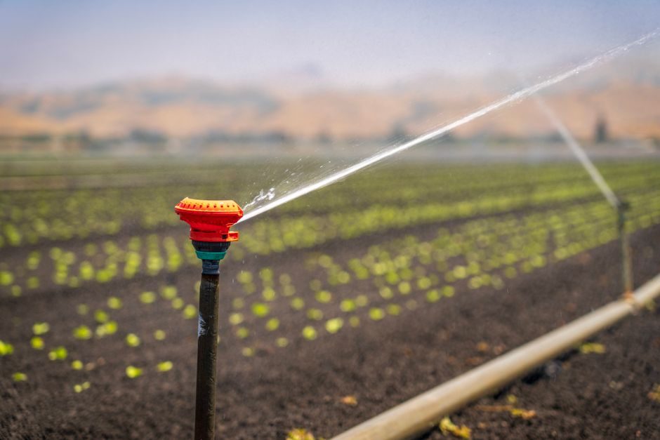
Wet, dry, deluge, preaction, and ESFR systems differ by the medium in the piping, the trigger that admits water, and the occupancy hazard tier they are designed to protect [S1][S3].
Selection is governed primarily by NFPA 13 — chapter 5 of the standard covers occupancy and commodity classifications, while the system-type chapter controls the actuation and water-delivery architecture [S3].
System Types by Actuation and Piping Medium
A wet pipe system holds water under pressure at every sprinkler and discharges immediately when a fusible link or glass bulb opens; it is the default choice wherever freezing is not a concern [S1]. A dry pipe system charges the aboveground branch lines with compressed air; opening a head vents the air, the dry-pipe valve trips, and water then travels into the piping — Northwestern University's design guide calls for a standard-pressure component rated 175 psig minimum working pressure with a 10% margin of safety on available water flow and pressure [S2]. Dry systems are specified for unheated warehouses, loading docks, parking decks, and exterior canopies where ambient temperatures could freeze a water-filled network [S1][S2].
Deluge and preaction variants are specialised dry-side architectures. A deluge system uses open sprinklers on a pipe that stays empty until a detection system actuates a deluge valve, dumping water simultaneously over the whole hazard — typical for highly flammable liquids or rapidly spreading fires. A preaction system requires a prior detection event to admit water into the pipe before the individual sprinkler fuses open, an arrangement used where accidental discharge would cause unacceptable damage to electronics, archives, or art. A complete dry-pipe specification submittal must include product data, shop drawings, wiring diagrams, delegated-design hydraulic calculations signed and sealed by a professional engineer, and field quality-control reports per NFPA 13 [S2].
NFPA 13 Occupancy Hazard Tiers
NFPA 13 chapter 5 defines five occupancy classifications by expected fire load: Light Hazard, Ordinary Hazard Group 1, Ordinary Hazard Group 2, Extra Hazard Group 1, and Extra Hazard Group 2 [S3]. Light Hazard covers offices, healthcare facilities, churches, and schools where combustibles are low and heat release stays modest. Ordinary Hazard Group 1 covers mechanical plants, laundries, and food-processing floors with no combustible stockpiles over 8 ft (2.4 m). Ordinary Hazard Group 2 raises the stockpile ceiling to 12 ft (3.7 m) and covers distilleries, barns, libraries, machine rooms, and auto repair shops. Extra Hazard Group 1 targets upholstery, sawmills, plywood, and textile operations dominated by highly combustible solids; Extra Hazard Group 2 is reserved for moderate-to-substantial flammable- and combustible-liquid inventories [S3].
Commodity classification is the second axis. Whereas occupancy is set by the use of the room, commodity class is set by the materials actually stored — Class I through Class IV reflect increasing plastic content, with cartoned unexpanded plastic and exposed expanded plastic driving the densest designs. The combination of occupancy and commodity drives sprinkler type, orientation, and spacing [S3]. A change of use inside a protected space can therefore invalidate an existing design — a fact routinely flagged in AHJ (authority having jurisdiction) reviews.
Design Density: GPM/SF by Hazard
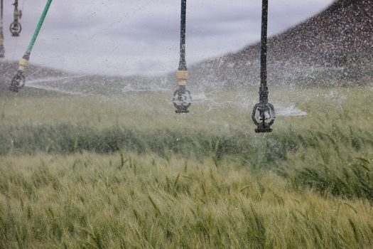
Design density is expressed as GPM/SF over a defined area of operation. As hazard climbs from Light to Extra Hazard, both the required density and the design area increase, forcing more water through larger orifice heads or wider spacing [S1]. For the FM Global HC-1 to HC-3 hazard categories (up to 30 ft ceiling), the published densities are 0.1 GPM/SF over 1500 SF (HC-1, both wet and dry), 0.2 GPM/SF over 2500 SF wet or 3500 SF dry (HC-2), and 0.3 GPM/SF over 2500 SF wet or 3500 SF dry (HC-3) [S1]. Dry systems always demand a larger design area than wet at the same HC tier because the trip time and water delivery lag compress the effective water-supply window.
ESFR (Early Suppression Fast Response) sprinklers are a separate track that does not use the GPM/SF area-density curve at all. ESFR heads are listed to suppress rather than control a fire, with high K-factor orifices, fast-response thermal elements, and ceiling-only storage arrangements. They are commonly specified for warehouse storage up to 40 ft of Class I–IV commodity and for certain cartoned plastic limits, but they require hydraulic analysis to confirm the ceiling-only design holds water at every head.
Comparison Across the Main System Types
Engineers usually weigh four criteria when picking among the main options: (1) activation speed, (2) water-in-pipe risk, (3) suitability for the hazard tier, and (4) hardware complexity. Wet pipe wins on speed and simplicity but is unsafe in freezing environments; dry pipe trades a measurable water-delivery delay for freeze tolerance; deluge gives the fastest discharge over the whole area but accepts accidental-water damage and the cost of a separate detection system; preaction halves the accidental-discharge risk by gating on detection, yet still leaves a small internal trip delay; ESFR delivers suppression-grade discharge from ceiling-only piping but locks the design into approved storage commodities and ceiling heights. [S1]
For cost-driven warehouses, an Ordinary Hazard Group 2 dry-pipe ESFR ceiling-only layout is often the lowest installed-cost path that still meets suppression listings; for data centres and clean rooms, a preaction double-interlock with gaseous suppression pre-discharge is the typical combination because accidental water release is the dominant risk. The link between hydrant underground supply and overhead sprinkler performance is direct, which is why a buried-thrust-block spec and a sprinkler system spec are usually reviewed together during AHJ plan review.
Engineering Limits, Failure Modes, and Acceptance
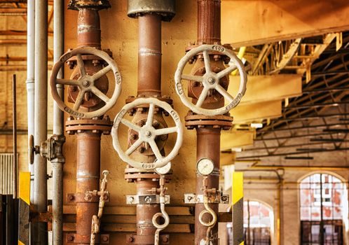
Dry-pipe systems have a hard ceiling on water delivery time — NFPA 13 limits the time from first sprinkler open to water discharge at the most remote head, which is why dry design areas are inflated by 1000 SF over the equivalent wet tier at HC-2 and HC-3 [S1][S2]. Compressor sizing, air-pressure set points, and accelerator/exhaustor selection must be calculated, not assumed, because a 10 psi air loss on a 40 psi trip is the difference between a 30-second discharge and an unacceptable 90-second one. The 10% engineering margin of safety on available water flow and pressure — including losses through water-service piping, valves, and backflow preventers — is the standard buffer applied to the contractor's flow test, but it does not excuse under-sized mains [S2].
Common acceptance failures on dry-pipe submittals are missing professional-engineer seals on hydraulic calculations, absence of the Contractor's Material and Test Certificate for Aboveground Piping, and unapproved working plans prior to fabrication [S2]. A second recurring failure is mis-classifying a space after fit-out — converting an OH-2 light-manufacturing room into an EH-1 plastics storage area will leave the existing spacing and density below the new requirement, and the only path back to compliance is re-spacing, adding heads, or upsizing the branch lines [S3].
Specification Outputs the AHJ Will Demand
For any dry-pipe submittal, the deliverable list reads: product data per component, shop drawings with plans/elevations/sections, wiring diagrams, a delegated-design package signed and sealed by a PE registered in the project state, and field test reports including the Contractor's Material and Test Certificate for Aboveground Piping [S2]. Sprinkler Occupancy Hazard Classifications, densities, and head spacing shall be as indicated on the drawings — a sentence that puts the load back on the engineer of record to fix the classification before drawings are issued.
For a clean cross-discipline review, pair the sprinkler design with the hydrant underground layout on the same plan set; the fire hydrant installation spec governs the lead-in that feeds the sprinkler riser, and the 30-year hydrant TCO math usually pins the available-flow assumption that the sprinkler hydraulic calculation rests on. Both the hydrant and the sprinkler system share NFPA flow-test methodology, so the field test is normally run once and shared.
Detailed specification references: asrs system, and shuttle system.