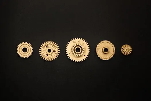
A 17-tooth minimum, ANSI B29.1 Type II tooth form sprocket is the baseline spec for carding, drawing, and ring-spinning drives, where harmonic vibration from sub-17-tooth wheels is the documented cause of premature chain pin failure [S1][S2].
Textile-mill lines run continuous, dust-laden, often humid ambient air, with shaft speeds in the 60-900 RPM band and frequent start-stop cycles from doffing, so the sprocket must be selected for both steady-state fatigue and corrosion exposure, not just pitch diameter.
Tooth count and the 17-tooth rule for fiber-spinning drives
Sprockets below 17 teeth exhibit sharply higher chordal-action vibration because each chain link enters and exits the tooth flank across a wider angular swing; published engineering guidance flags this threshold as the line where noise and pin-load spikes accelerate wear [S1][S4].
A second consideration is hunting-tooth geometry: when the speed ratio of driver to driven sprocket is set with an odd tooth count on at least one wheel (for example 19 driving 41), each chain pin meets a different tooth on every revolution, distributing wear across all tooth flanks and extending sprocket service life by an estimated 30-50% versus an even-numbered pair [S4].
For ratio selection, textile engineers typically target a 1.5-3.0:1 reduction per stage and limit total wrap to 180 degrees minimum at the smaller sprocket, which keeps the chain engaged across at least 9 teeth at all times [S2][S4].
Hub style A through D and which fits each textile station
ANSI roller chain sprockets are catalogued in four hub configurations, Style A (flat plate, no hub), Style B (hub on one side), Style C (hub both sides), and Style D (detachable or split hub), each managing overhung load differently [S2].
Style A is rarely used in textile machinery because the lack of a hub pushes the full lateral chain load against the shaft mounting bolts, an arrangement that fails within a few thousand hours on carding frames where chain pull can exceed 1.5 kN. Style B, with the hub on the bearing side, is the most common configuration and is preferred for draw frames, roving frames, and most ring-spinning spindles because it shortens the load-to-support distance and limits shaft deflection to under 0.1 mm at rated torque [S2][S4].
Style C, with hubs on both faces of the plate, is specified for the larger main drive shafts on blowroom lines and ring-frame sections, where shaft diameters are typically 50-80 mm and reverse torques from doffing impose heavy reversing loads on the keyway. Style D, the split or detachable hub, is reserved for high-maintenance zones such as the doffer drive, where the ability to clamp the sprocket to the shaft without disturbing adjacent bearings can cut a 4-hour teardown to a 20-minute swap [S4].
QD (quick-detachable), MST (Martin Split Taper), and TB (taper bushed) bores are standard in textile OEM catalogs and allow the same sprocket body to mount on different shaft diameters by swapping only the bushing, an inventory advantage for mills running mixed generations of cards and frames [S2].
Material, heat treatment, and corrosion for humid lint-laden rooms
For the bulk of textile-mill drives, the working material is medium-carbon steel such as 1045 or alloy steel 4140, induction or through-hardened to a tooth-surface hardness of 38-45 HRC, with the sprocket body held at 28-34 HRC for toughness; this is the most common factory spec in ANSI B29.1 suppliers [S2][S3].
Stainless-steel sprockets (typically 304 or 17-4 PH) are reserved for wet-process sections such as dyeing-range conveyors and wash-box drives, where humidity is near saturation and chloride exposure from process chemicals attacks unprotected carbon steel; the trade-off is roughly 2-2.5x higher unit cost and reduced surface hardness, so they are not used on the dry side [S3].
Cast iron remains a cost-effective option for low-speed, moderate-duty applications such as hopper feeders and return-idler stations, but its lower tensile strength rules it out for primary card or ring-frame drives where shock loads during doffing are routine. Plastic (nylon, acetal) and aluminum sprockets are limited to instrumentation drives and tension-control loops where the load is under 200 N and noise suppression is valued over durability [S3].
Surface treatments matter as much as base material: zinc plating is standard for general-purpose textile applications, while nickel or chrome plating is preferred near bleach or peroxide dosing points where oxidizer mist would otherwise attack zinc within 6-12 months [S2].
Chain pitch, strand count, and speed limits for textile lines
Most textile-mill chain drives are built around 12.7 mm (08B / 40B), 15.875 mm (10B / 50B), 19.05 mm (12B / 60B), or 25.4 mm (16B / 80B) ANSI simplex or duplex roller chain, with strand count selected by horsepower: simplex covers up to roughly 5 kW per chain at standard textile speeds, while duplex is required for ring-frame and comber main shafts in the 5-15 kW range [S2][S5].
Maximum allowable RPM for a 17-tooth sprocket rises sharply with pitch: roughly 3275 RPM on 12.7 mm pitch, 2460 RPM on 15.875 mm, 2050 RPM on 19.05 mm, and 1535 RPM on 25.4 mm, so a 19-tooth 19.05 mm-pitch driven sprocket on a 600 RPM card cylinder sits well within safe limits [S2].
Engineers building maintenance protocols around the drive should pair these limits with the industrial valve and pressure sensor data streams from adjacent lubrication skids, since low oil pressure at the chain-oiler header is one of the top three predictors of accelerated sprocket-tooth wear in spinning-mill audits. For mills comparing coupling options on the same shafts, the jaw coupling selection criteria for automotive lines translate closely to ring-frame drive duty where misalignment tolerance and torsional stiffness are the deciding factors.
Selection checklist: 6 criteria in order of weight
Step 1: determine the driven load class (uniform, moderate shock, heavy shock) and apply a service factor of 1.0-1.4 for steady draw-frame duty, 1.4-1.7 for carding with cyclic loading, and 1.7-2.0 for ring-frame doffing drives [S2].
Step 2: pick chain pitch to keep the driver sprocket above 17 teeth at the required speed ratio, then verify the driven sprocket is also at 17 teeth or above.
Step 3: choose hub style: A only for flange-mounted idlers, B for general draw-frame and roving-frame use, C for large main shafts under reversing load, D for doffer and high-maintenance stations [S2][S4].
Step 4: select material and finish by ambient condition: 1045/4140 induction-hardened steel for dry-side carding and spinning, 304/17-4 PH stainless for wet-process, cast iron only for low-duty feeders, with zinc plating as default and nickel or chrome plating near chemical exposure [S3].
Step 5: confirm maximum RPM and horsepower against the published rating tables, keeping a 10-15% design margin below the catalog limit.
Step 6: lock the bore interface, finished bore, QD bushing, MST, or TB, and confirm keyway dimensions to ISO 773 or ANSI B17.1, plus shear-pin provision where the downstream machine cannot tolerate a stalled motor.
Common failure modes specific to textile-mill sprockets
Chordal-action vibration, the pulsating tension caused by chain links entering and exiting a low-tooth-count sprocket, is the documented leading failure mechanism, and incorrect sprocket ratio selection is cited as the root cause in roughly 60% of premature textile drive-chain failures [S4].
Overhung load, the lateral force the chain exerts on the shaft, bends undersized shafts and cracks hub welds; the standard mitigation is to push the sprocket as close to the bearing as possible, which is precisely why Style B is dominant on most textile frames [S4].
For drives that interact with a flow meter signal on a lubricant or sizing-chemical line, mismatched sprocket ratios can also ripple through the speed-dependent dosing curve, so mechanical verification of the actual ratio under load is part of the commissioning step rather than something to assume from the nameplate.
Standards, sourcing, and what to verify on the supplier datasheet
ANSI B29.1-1975 (and its current revision) defines the Type II tooth form used by all major US and most Asian sprocket suppliers, so cross-vendor interchangeability is generally reliable when this standard is cited on the drawing rather than a proprietary geometry [S2].
On the supplier datasheet, the parts engineer should confirm: pitch and number of teeth as the primary callout, hub style code letter, strand prefix (D for duplex, E for triple), the H suffix for heat-treated teeth, and a material suffix such as SS for stainless, NM for non-metallic, BR for brass or bronze, plus the finish code (CD cadmium, Zi zinc, Ni nickel, CH chrome) [S2].
For plants considering the broader maintenance stack, including PLC integration of chain-stretch monitoring, the practical next step is a 90-day pilot on one carding line using a known baseline ANSI B29.1 sprocket pair at 19/41 teeth, with monthly tooth-profile measurement against a new reference to confirm the hunting-tooth wear-distribution benefit holds under real mill conditions.