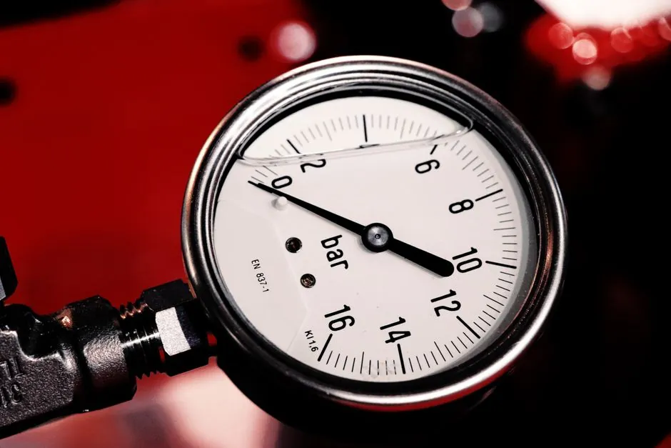
A steam-trap safety factor is a dimensionless multiplier applied to the running condensate load to derive the required trap discharge capacity, with manufacturer recommendations spanning 1.5 to 5.0 across the major trap types [S2]. The factor is not a thermal-warm-up calculation: it is a screening shortcut that forces the rated capacity chart to read high enough to cover start-up, cold-pipe condensation, and short-term load swings [S1][S5].
Process engineers treat the multiplier as a 60-second sanity check against an OEM capacity chart, not as a substitute for differential-pressure selection. The capacity ratio of selected to required trap capacity is then classified as UNDERSIZED below 1.00, ACCEPTABLE between 1.00 and 1.15, RECOMMENDED between 1.15 and 1.50, and OVERSIZED above 1.50 [S5]. For comparison context on related instrument sizing math, DP transmitter range sizing for orifice flow meters walks the same multiplier-then-chart pattern for a different primary element.
Safety Factor Range by Trap Type and Service
Manufacturer-published safety factors for routine drip, tracer, and steady process-heating service cluster between 1.5 and 3.0, with inverted-bucket and float-and-thermostatic designs typically landing at 2.0, thermostatic designs at 1.5 to 2.0, and thermodynamic disc traps between 1.5 and 3.0 [S2][S4]. Warm-up service, where the steam main is cold and condensing rate spikes during pressurisation, requires the higher end of the range, commonly 3.0 to 4.0 [S3][S4]. Heavy process equipment with slow rotational mass, such as large jacketed vessels or rolls, is documented at 4.0 in Nicholson guidance [S7].
The capacity band itself is broad: Armstrong notes that users must apply a safety factor to avoid undersizing at start-up, while TLV's reference band of 1.5 to 5.0 covers the published spread across major OEMs [S1][S2]. Watson McDaniel's published selector steps the user through 1, 1.5, 2, or 3 as discrete options tied to drip, tracer, and warm-up categories [S4]. A worked JMP example multiplies a 2000 PPH running load by 1.5 to land on 3000 PPH rated capacity, then derates by 1/2 PSIG differential on a low-pressure return [S3].
How the Multiplier Interacts with Differential Pressure
Required trap capacity is the product of the running condensate load and the safety factor, and that number is then read against the OEM capacity chart at the actual operating differential pressure, which equals inlet steam pressure minus back pressure [S5]. Differential pressure is the second leg of the calculation: a 150 PSIG inlet with 0 PSIG back pressure produces roughly 150 PSIG DP, while the same inlet discharging into a 50 PSIG return header drops usable DP to 100 PSIG and can cut published capacity by 30 to 50 percent depending on trap model [S5].
Vertical lift in the condensate return line is a real, quantifiable back-pressure cost: 1 PSIG is consumed for every 2.31 ft of vertical rise above the trap discharge, plus any header pressure in the return system [S4]. The safety factor cannot fix an oversized lift. A trap correctly sized at 1.5 with adequate DP will still fail if the return line imposes 20 PSIG of artificial back pressure at the discharge. Engineers reading the JMP example apply the 1.5 factor, then read the chart at the corrected 1/2 PSIG DP, not at the saturated-steam inlet pressure [S3].
Selection Matrix: Service to Recommended Multiplier

The four most common services map cleanly to a multiplier band. Drip legs on insulated steam mains at 50 to 150 PSIG run 2.0 as the baseline, with 3.0 applied on uninsulated mains in cold ambient [S4]. Tracer lines on chemical or fuel-oil piping are typically 1.5 to 2.0 once the line is at temperature, with a separate warm-up factor of 3.0 to 4.0 if the tracer is started cold [S2][S4]. Process heating with steady, well-controlled load, such as clean steam on a pharmaceutical skid, drops to 1.5 with a documented surge allowance [S2]. Heavy rotating equipment and large batch reactors, where the cold mass dominates condensate rate for the first 10 to 20 minutes, use 4.0 per Nicholson's worked example on a 1483 lb/h load landing at 5932 lb/h required capacity [S7].
Capacity ratio bands give the engineer a second-tier check: an UNDERSIZED ratio below 1.00 is automatic rework, an ACCEPTABLE 1.00 to 1.15 reading means the chart pass was correct, a RECOMMENDED 1.15 to 1.50 reading is the design sweet spot, and anything above 1.50 is OVERSIZED and likely to accelerate seat wear on thermodynamic and inverted-bucket designs [S5]. The capacity-ratio interpretation is a screening band, not a manufacturer rating, and trap-specific published margins should override it when present [S5].
Why Oversizing Is Its Own Failure Mode
Armstrong's conservation guide warns that sizing for start-up loads results in oversized running traps, which then wear prematurely, particularly on thermodynamic disc and inverted-bucket designs where a too-large orifice fails to modulate at low condensate rates [S1]. A trap with a 5.0 multiplier on a steady drip will pass air and water correctly at start-up, then slam shut and chatter at part load, accelerating seat wear and shortening service life to a fraction of its rated cycle count [S1][S2].
TLV's selection guide ties the safety factor directly to life-cycle cost: a 1.5 multiplier on steady load yields a smaller, cheaper trap that lasts longer in service, while a blanket 4.0 on every application inflates both purchase and maintenance cost without proportional reliability gain [S2]. The reasonable practice is to split the calculation: one trap for start-up with manual dump or supervised bypass, and a separate running trap sized at 1.5 to 2.0 for the steady condensate load once the system is hot [S4].
Common Failure Modes and Operator Pitfalls
Undersized traps at start-up are the headline failure: cold mains condensing at several times the running rate overwhelm a 1.5 multiplier, water hammers the line, and downstream equipment receives wet steam [S1][S4]. Oversized traps at running load are the second-most-common failure: thermodynamic disc traps with too-large orifices pass live steam at part load, while thermostatic traps with oversized bellows fail to reach their closing temperature and discharge continuously [S1][S2].
Back-pressure mistakes are the third pitfall. Engineers who apply 1.5 or 2.0 multipliers but then read the OEM capacity chart at full inlet pressure, ignoring the return header and lift, end up with a trap that looks correctly sized on paper but blows its discharge orifice on the first cold start [S4][S5]. For a related internals decision that affects steam quality upstream of the trap station, steam separator internals: mesh pad vs vane pack and steam separator upstream of control valve cover the upstream hardware that changes the wet-steam load the trap must handle.
Standards, Sourcing, and Verification Path
No single ISO or ASME standard mandates a specific safety factor value: the multiplier is an OEM and engineering-judgment call, with manufacturer capacity charts per ASME PTC-published test methods supplying the underlying rated-discharge data [S1][S2][S4]. The published reference band of 1.5 to 5.0 across OEMs comes from Armstrong, TLV, Watson McDaniel, and Nicholson engineering documents, not from a regulatory standard [S1][S2][S4][S7].
Verification path is short: pull the running condensate load in lb/h from the heat-balance or steam-table calculation, multiply by the service-appropriate factor, subtract the actual return-line back pressure, and read the corrected differential pressure on the OEM capacity chart for the candidate trap body. Trackable signals for 2026 are OEM-published revisions to capacity charts and any movement in the published 1.5 to 5.0 band on the TLV and Armstrong engineering pages. Background on the trap mechanism itself, including inverted-bucket, float-and-thermostatic, and thermostatic operating principles, is covered in the steam trap encyclopedia entry.
For component-level specifications, see steam separator, and fire safety.