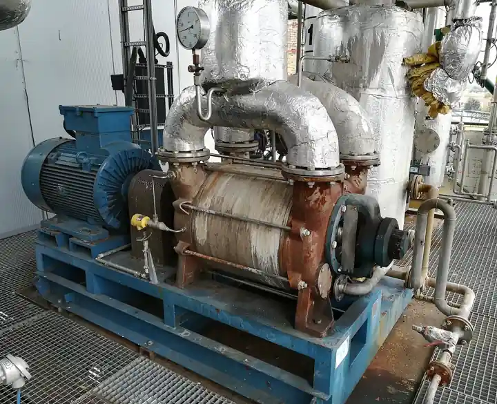
A steam ejector is a static device that produces vacuum with no moving parts: high pressure motive steam expands through a converging and diverging nozzle to supersonic velocity and very low static pressure, entrains process vapor from the suction connection in a mixing chamber, and a diffuser then decelerates the mixture, converting velocity back into pressure so the combined stream discharges at an intermediate pressure. There is no rotor, no oil, no clearance to wear in the conventional sense, and nothing to lubricate. Industry calls the single device a vacuum ejector or steam jet ejector, and calls a multistage assembly with its condensers a steam jet vacuum pump, which is honest: the assembly pumps, the ejector stage compresses. Motive pressures run 3 to 40 bar with most systems designed around 10 to 16 bar plant steam, and suction pressures run from rough vacuum at a few hundred mbar down to the 0.1 mbar class in five and six stage trains with intercondensers.
Procurement engineers meet these systems on crude vacuum columns in refineries, on chemical and pharmaceutical distillation and degassing, on steel and aluminum melt degassing, on freeze drying backing duty, on chlorine and vinyl chloride monomer handling where oil sealed machines corrode, and on deaerator and tank vehicle loading vacuum. The decision this page settles is narrow and practical: how many stages and what condenser arrangement the duty earns, what motive steam pressure and dryness the design must assume, how cooling water temperature sets summer capacity, and what the RFQ must state about gas load composition so the train is sized to the process rather than to a sales curve. The answer lands as an RFQ line set, and every chapter below feeds that line set.
This page treats the steam ejector as a purchasing object: how the nozzle and diffuser geometry converts pressure into vacuum, what compression ratios and entrainment ratios actually promise, which stage and condenser arrangements suit which suction pressure, how motive steam quality makes or quietly breaks capacity, and how all of it combines into a defensible RFQ. It is written for engineers who issue purchase specifications, not for readers who want a brochure summary.
Chapter 1 / 06
What a Steam Ejector Is and What Is Being Decided
The physics is the product. Inside the casing sit three machined flow passages and nothing else: a motive nozzle, a mixing chamber around it, and a diffuser downstream. Motive steam at 3 to 40 bar enters the nozzle, which first converges to accelerate the flow to the speed of sound at the throat and then diverges, where the expanding supersonic jet drops to a static pressure far below the process suction pressure. That low pressure region is the pumping mechanism: process vapor is pushed into the mixing chamber by the pressure difference, momentum from the steam jet accelerates it, and the mixed stream enters the diffuser, decelerates, and recompresses to a discharge pressure above the suction pressure. The machine is a momentum exchange device with the same heritage as the venturi tube, and every performance claim in a catalog reduces to how well those three passages were machined and matched.
What is actually being decided in this purchase is a utilities contract wearing the clothes of an equipment order. A steam ejector system spends motive steam and cooling water continuously whether the process needs vacuum at that moment or not, and the buyer commits to that operating cost for the life of the plant. The decisions are: stage count, set by the ratio of discharge to suction pressure with compression ratios of 4 to 10 per stage as the economic band; condenser arrangement, surface or direct contact, intercondensers or none, set by cooling water quality and condensate recovery value; motive steam conditions, pressure, dryness, and the margin held against header droop; and materials, set by the corrosive species in the load. An ejector bought on a single suction pressure number without a load breakdown will either be oversized, spending steam it never needed, or collapse in summer when the cooling water warms and the back pressure on each stage rises.
The neighbor map is worth drawing early, with the full comparison reserved for chapter 5. The jet pump is the parent family: an eductor pumping liquid with a liquid or gas motive, and the steam ejector is the steam driven gas handling branch. Against mechanical machines, the liquid ring vacuum pump is the tolerant, water cooled rival that shares condensable load capability; the rotary vane pump is the oil sealed small package option; the vacuum generator, a compressed air venturi device, serves intermittent point of use duty at negligible first cost and poor energy efficiency; and the dry screw machines described elsewhere in this encyclopedia own oil free chemical duty at moderate depth. The steam ejector holds the ground all of them concede: the harshest and hottest streams, corrosive and condensable loads that wreck mechanical clearances and oils, deep vacuum at high throughput, and installations where a machine with no moving parts and no motor is the reliability strategy itself.
Standards honesty comes early because ejectors sit outside the pump codes. There is no API or ISO product standard for steam jet ejectors; the governing reference is the Heat Exchange Institute (HEI) Standards for Steam Jet Vacuum Systems, which fixes how performance is stated and tested, and its companion standards for direct contact barometric and low level condensers and for surface condensers govern the condenser shells. Pressure vessel sections of the ASME code apply to the condensers and to any coded casings. What no standard fixes, the purchase document must: the load analysis, the motive and cooling water conditions, the acceptance test method, and the noise guarantee. Those four lines, written by the buyer, are what make two ejector quotations comparable at all.
The ejector never works alone, and the RFQ should name its station. Upstream of the motive nozzle: a steam separator and a Y strainer with a drip leg and steam trap, because wet steam erodes the nozzle throat faster than any process contaminant. Downstream: intercondensers and an aftercondenser, a barometric leg or condensate pumps, a discharge silencer where the tail vents to atmosphere, and vacuum breaking hardware. Monitoring is three instruments: a pressure transmitter on the suction, a pressure transmitter on the motive header, and a temperature transmitter on the discharge or cooling water return. An RFQ that buys the stages and forgets the station buys a system that draws its vacuum on paper and loses it in the pipe.
Chapter 2 / 06
How the Nozzle and Diffuser Make Vacuum
Start with the nozzle, because everything downstream is consequence. The converging section accelerates the motive steam until it reaches sonic velocity at the throat, typically Mach 1 at the narrowest point; the diverging section then lets the supersonic stream expand, trading pressure and temperature for velocity until the jet leaves the nozzle at Mach 2 to 3 class speeds, on the order of 1,000 m/s for typical plant steam conditions, with a static pressure orders of magnitude below the suction pressure at deep vacuum stages. That expansion is why motive pressure cannot be traded away: below the design pressure the expansion is incomplete at the nozzle exit, the jet is under expanded or oscillating, and entrainment collapses disproportionately. This asymmetry is the single most important operational fact about ejectors, and it earns the 10 percent margin rule that appears in every reputable application note: size the ejector at the lowest sustained header pressure, not the boiler nameplate.
Entrainment is the pumping. Process vapor crosses into the mixing chamber, where the supersonic jet shears and accelerates it, and the two streams exchange momentum across a conical mixing region until they leave the chamber at a common velocity somewhere between the two. The entrainment ratio, kilograms of process gas entrained per kilogram of motive steam, is the efficiency statement of the machine, and it is set by the nozzle to diffuser geometry and the pressure conditions rather than by anything adjustable on site. The honest numbers by depth: a roughing stage at 50 to 100 mbar entrains perhaps 5 to 10 kg of gas per 100 kg of steam, while a deep vacuum stage at 0.1 mbar may spend 50 to 100 kg of steam per kilogram of non condensable gas. That is why multistage trains exist: condensers between stages remove the steam so only the process gas and inerts carry forward, and the motive consumption of the train stays finite.
The diffuser closes the cycle. Geometrically it is a venturi tube run in reverse: a deliberate deceleration path rather than a metering one. Its converging inlet decelerates the mixed supersonic stream through a shock front, which is the point of maximum compression and maximum noise, and the diverging outlet continues the deceleration, recovering static pressure up to the discharge condition. The diffuser throat diameter against the nozzle diameter is the fixed geometry that sets the compression ratio a stage can hold, and stable operation has two regions: below a critical discharge pressure the stage holds full capacity regardless of small back pressure changes, and above it the shock wave detaches from the diffuser throat and the stage breaks, dumping motive steam backward into the suction. This is why condenser fouling and warm cooling water are not efficiency problems but stability problems: they raise interstage pressures stage by stage from the back of the train forward until the first stage that exceeds its critical pressure collapses, and the operator sees sudden total loss of vacuum rather than gradual decline.
Condensers are stages of the system in the same sense that impellers are stages of a pump. An intercondenser between ejector stages condenses the spent motive steam out of the stream, so the next stage handles process vapor and non condensables only, cutting its required steam consumption dramatically; a two stage system with one intercondenser typically spends 30 to 50 percent less steam than the same duty with none. Surface condensers pass cooling water through tubes and keep condensate separated, recovering clean condensate and suiting fouling services at higher cost; direct contact condensers spray cooling water into the vapor, cost less, transfer heat better, and mix everything, discharging to a barometric leg of about 10.3 m at atmospheric pressure into a hotwell, or to a low level condenser with extraction pumps. The choice is an economics and water chemistry decision made in chapter 4, but the physics floor is fixed here: the condenser must remove the latent heat of the motive steam it receives, and cooling water at its warmest design temperature must still hold the interstage pressure below each stage critical value. Moving that water is ordinary plant duty for a centrifugal pump and a cooling tower, but the flow and temperature they deliver are as much a part of the vacuum system as the steam itself.
Compression ratio bounds the staging. One ejector stage performs usefully at compression ratios of about 4 to 10, with the low end typical at deep vacuum and the high end achievable at rough vacuum with generous steam. A single stage taking atmospheric discharge therefore bottoms out near 100 to 150 mbar suction; two stages reach the 10 to 20 mbar class; four and five stage trains with intercondensers reach 1 mbar and below; and trains reaching the 0.1 mbar class add booster ejectors ahead of the roughing stages, boosters sized to run at absolute pressures where condensing is no longer possible and only momentum transfer works. Above roughly 40 bar motive the returns flatten, and below about 3 bar a steam ejector is usually the wrong tool; both boundaries belong in the RFQ conversation so the steam system is negotiated with eyes open.
Superheat and dryness deserve one paragraph because they are quietly decisive. Wet steam carries water droplets at jet velocity, and they machine the nozzle throat and diffuser inlet the way a slurry machine cuts soft iron; a separator, strainer, and trap on the motive line are cheaper than an annual nozzle set. Superheat beyond about 25 to 30 deg C raises steam specific volume and lowers the mass flow a fixed nozzle passes, and with it the entrainment ratio, so heavily superheated headers need derate curves from the maker rather than optimism. Saturated or lightly superheated steam at a stable pressure is the design condition the whole train should assume.
Chapter 3 / 06
Types, Construction, and Duty Boundaries
Stage and condenser architecture defines the product types. A single stage ejector, no condenser ahead of it, discharges to atmosphere or to a plant vent and covers rough vacuum duty from atmospheric suction down to roughly 100 to 150 mbar: deaerator off gas, tank blanketing, simple venting. A multistage non condensing train runs two or three ejectors in series with no intercondensers, spending more steam but eliminating the cooling water service and the condensate handling entirely, which suits intermittent duty and sites with no cooling water at the point of use. A multistage condensing system, the workhorse of process vacuum, alternates ejector stages with intercondensers and finishes with an aftercondenser for silencing and vapor removal; this is the architecture behind the single, two, three, and multistage steam jet vacuum pump assemblies of the Schutte and Koerting and Graham literature listed in the sources, and it is what most RFQs should be asking about below about 50 mbar.
Booster ejectors extend the train downward. A booster is a large first stage designed to run at absolute pressures where its discharge is still below the condensing point, so it discharges directly into the next ejector without an intercondenser between them; deep vacuum trains for steel degassing and process distillation pair a primary and sometimes a secondary booster ahead of a three or four stage roughing system with condensers. Boosters are normally furnished with a pressure actuated or process interlocked steam valve, because running boosters at process pressures that do not need them is pure steam waste, and part load economics is where booster systems win or lose their operating case.
The thermocompressor is the sibling duty inside the same hardware. A thermocompressor, the TVR of evaporator engineering, uses 8 to 16 bar motive steam to entrain low pressure vapor, often the vapor boiled off in an effect, and recompress it to a useful intermediate pressure, recycling latent heat instead of spending new steam. Geometrically it is an ejector tuned for a different job, and it appears in the types discussion here because RFQs cross the two constantly; the boundary is duty, not shape. Vacuum ejector stages optimize for maximum compression at minimum suction pressure; thermocompressors optimize for entrainment ratio at modest compression, and a supplier asked for one while quoting the other will happily sell an inefficient machine.
Materials are few and consequential. The baseline body is cast iron with a stainless steel nozzle and diffuser insert, correct for steam, air, and most hydrocarbon service. Where the load carries chlorides, chlorine traces, or acid gases, bodies and internals move to 316L stainless, and Monel or Hastelloy C class alloys serve the chlorine, vinyl chloride monomer, and HCl services that motivate ejectors over mechanical pumps in the first place. The diffuser bore and nozzle throat are the two precision surfaces: their diameters and finishes are the performance certificate of the machine, which is why a worn nozzle is replaced rather than filed, and why spare nozzles and diffusers ship with the original order. Erosion, corrosion, and scale are the only wear modes, and chapter 6 prices them.
The duty boundaries are about the load, not just the pressure. Ejectors tolerate streams that end mechanical pumps: condensable and corrosive vapors, entrained droplets, and hot gases, because there is no oil to pollute and no close running clearance between rotating parts. They do not tolerate, at any design, a non condensable load larger than the train was sized for, because inerts pass every condenser and accumulate in the back stages; air in leakage beyond design is the classic capacity killer found in chapter 6. And they are loud: a bare stage discharges through a shock front, and silencers, insulation, and aftercondensers bring the package to the mid 80s to low 90s dB(A) class at one metre, a line the RFQ should pin down before the neighbor does. The architecture table below fixes the boundaries a specifier can quote.
System type
Typical suction range
Utilities character
Where it earns its cost
Single stage, non condensing
atmospheric to about 100 to 150 mbar
Steam only, highest specific consumption
Deaerator vent, tank blanketing, simple evacuation
The table below decodes the datasheet lines that decide whether a quoted system matches the duty. Each row is purchase defining; the paragraphs after it explain what to demand and what a weak answer looks like.
Parameter
Typical range or options
What it decides
Design suction pressure
0.1 mbar to atmospheric by train
Stage count, booster need, and the whole utility case
Gas load, split by species
kg/h air equivalent plus kg/h condensables
Nozzle sizes; whether inerts or vapor governs the design
Non condensable allowance
air equivalent 0.5 to 2 kg/h small systems, tens on process trains
Back stage sizing and air in leakage margin
Motive steam pressure and dryness
3 to 40 bar; design 10 to 16 bar; dryness 98 percent plus
Entrainment capability and nozzle life
Motive steam consumption
tens of kg/h per stage to tonnes/h on boosters
The lifetime operating cost of the system
Cooling water temperature
design at warmest site water, commonly 28 to 33 deg C
Corrosion life in chloride, chlorine, and acid service
Noise with silencer
mid 80s to low 90s dB(A) at 1 m target
Operator exposure and site acceptance
The load analysis is the real specification, and no row of the table substitutes for it. Condensable vapor and non condensable gas behave completely differently in a train: vapor condenses in the first intercondenser it meets, inerts pass every condenser and accumulate, so the back stages must be sized for the air equivalent load and the front stages for total vapor. The RFQ should state kilograms per hour of each, with air and other inerts named by gas, and it should state the air in leakage allowance assumed, typically 0.5 to 2 kg/h for small systems and tens of kilograms per hour for large train systems, because underestimating in leakage is the single most common cause of a system that never reaches design vacuum. A quotation written against a duty description that says only 5 mbar is a price tag, not a design.
Motive steam conditions deserve their own paragraph because they are the utilities contract in miniature. The RFQ should state the minimum sustained header pressure with the design margin, in practice sizing at the pressure the header holds on its worst day, commonly 10 percent below nominal, and state dryness or superheat in numbers. The station hardware follows from the physics of chapter 2: a separator and Y strainer on the motive line at each ejector takeoff, a drip leg below the strainer drained through a steam trap, and a pressure transmitter on the header with a low alarm ahead of the point where stages begin to break. Steam consumption is verified, not assumed: an orifice plate flowmeter on the main motive header, or a flow nozzle where the permanent pressure loss matters, turns the maker steam tables into a measured number, and the difference between those two figures is usually the strongest argument in the first energy audit.
Cooling water sets summer capacity, and the datasheet must say so. Intercondensers hold interstage pressures only if the water removes the motive steam latent heat at its warmest temperature, so the design point is the maximum summer water temperature, commonly 28 to 33 deg C by site, not the annual average. The temperature transmitter on cooling water return, read against the condenser design terminal difference, tells the operator whether fouling is eating the critical pressure margin months before a stage breaks. Where the water is hard or biological, direct contact condensers trade cleanliness for condensate contamination, and surface condensers trade first cost for recoverable condensate; both belong in the RFQ with their tube materials stated, and the choice is made on water chemistry and condensate value, not on catalog preference.
The arrangement table below compresses the staging decision into the form a specification meeting can argue from; the selection chapter then applies it to real duties.
Duty target
Arrangement to specify
Verify before order
Rough vacuum, 100 to 150 mbar and coarser
Single stage with discharge silencer
Motive margin at header minimum; noise at 1 m
10 to 50 mbar continuous process
Two to three stage with intercondensers
Summer water temperature in the stage sizing
1 to 10 mbar distillation or drying
Three to five stage condensing system
Load split condensable versus inert; air allowance
0.1 to 1 mbar degassing or deep vacuum
Booster pair ahead of roughing condensing train
Booster steam shutoff interlock; spare nozzles
Chlorine, VCM, or HCl laden streams
Condensing train in 316L, Monel, or Hastelloy C
Material certificates; scrubber on aftercondenser vent
Vapor recompression on evaporators
Thermocompressor (TVR), not a vacuum train
Entrainment ratio at motive minimum; control range
Chapter 5 / 06
Selection Decision Factors and RFQ Language
The decision sequence below runs as a checklist in a specification meeting, and each step eliminates a class of quotations before any price comparison starts.
Fix the operating suction pressure the process actually needs, not the best ever achieved, and fix the gas load at that pressure in kilograms per hour.
Split the load into condensable vapor and non condensable gas by species, name the air in leakage allowance, and state the dissolved gas contribution if the process releases it.
State motive steam honestly: minimum sustained pressure with margin against droop, dryness or superheat, and the tonnes per hour the plant can actually dedicate.
State cooling water maximum summer temperature, available flow, and quality, and decide surface against direct contact condensers on chemistry and condensate value.
Pick the staging from the chapter 4 table against the compression ratio band, and demand the maker stage by stage pressure cascade written into the quotation.
Choose materials against the corrosive species, and order spare nozzles, diffusers, and gaskets with the machine rather than after the first outage.
Name the station: separator, Y strainer, drip leg with steam trap and condensate pot, header pressure transmitter, suction pressure transmitter, discharge temperature transmitter, silencer, vacuum breaking hardware, and pressure vacuum relief valve protection on the hotwell or vent tank.
Fix the evidence: HEI basis performance curves, the acceptance test method at site conditions, and the noise guarantee with measurement distance stated.
Against the neighboring technologies, the honest comparison runs as follows, and it belongs here in the selection chapter rather than in the page title. The liquid ring vacuum pump is the cheapest machine to operate where service water exists and the ultimate requirement is modest, near 25 to 30 mbar wet; it tolerates condensables like the ejector does, and the two appear staged together on crude vacuum columns, ejector first and ring machine backing. The rotary vane pump holds lower ultimate in a small package but brings oil, which corrosive and condensable streams destroy. The dry screw machines own oil free chemical duty in the 0.01 to 1 mbar band at mechanical prices and mechanical reliability. The vacuum generator serves intermittent point of use duty wherever shop air already exists and energy efficiency does not matter. And the jet pump, the liquid eductor sibling of this same family, pumps water from sumps and tanks rather than making vacuum at all. The steam ejector wins when any three of these are true: the load is corrosive or condensable beyond what mechanical machines survive, steam is already at the battery limit and cheap, deep vacuum at high throughput is required, and the plant values a machine with no moving parts over a machine with a motor. When steam is expensive and the duty is shallow, the same honest arithmetic points away from this page, and the RFQ should follow the arithmetic.
The application map below turns that comparison into a table the project file can carry.
Application
Construction to specify
Check before order
Crude vacuum column, refinery
Booster plus condensing train, or ejector plus liquid ring vacuum pump hybrid
Load at top vacuum; sour water corrosion allowance; steam balance
Chemical and pharma distillation
Two to five stage condensing system with surface intercondensers
Solvent condensability; product recovery from hotwell
Steel and aluminum degassing
Booster pair with interlocked steam valves, corrosion resistant trim
Cycle steam consumption; dust in the load
Freeze drying backing duty
Condensing train or hybrid with mechanical backing
Water vapor load split with condenser; oil free requirement
Chlorine and VCM service
316L or Monel or Hastelloy C condensing train with scrubbed vent
Material certificates; aftercondenser vent treatment
Deaerator and tank vehicle vacuum
Single stage or two stage compact unit with silencer
Motive margin; noise at boundary; intermittent duty steam valve
The RFQ block should be written once and reused. A complete block reads: design suction pressure with the process basis; gas load in kilograms per hour split into condensables by species and non condensables as air equivalent, with the air in leakage allowance stated; discharge pressure and destination; motive steam minimum sustained pressure, dryness or superheat, and flow with an orifice plate flowmeter or flow nozzle to verify it; cooling water maximum summer temperature, flow, and quality with tube or spray materials; condenser arrangement, surface or direct contact, intercondenser count, barometric leg height or low level extraction pumps; stage by stage pressure cascade and steam consumption per stage at design and at minimum motive; body and internals materials with certificates for wetted parts in corrosive service; the station hardware, separator, Y strainer, drip leg with condensate pot and steam trap, suction and motive pressure transmitter, discharge temperature transmitter, vacuum breaker check valve arrangement, discharge silencer with guaranteed noise at a stated distance, and a safety relief valve where the discharge manifold can be isolated while steam flows; spare nozzles, diffusers, and gaskets priced with the order; and the acceptance basis, HEI performance curves with the site test method and witness level. A quotation returned without the load split or the summer cooling water design point is incomplete at any price.
Chapter 6 / 06
Installation, Standards, Failure Modes, and Maintenance
Installation quality decides whether the geometry sees its design life, and most of it is steam discipline. Take the motive supply from the top of the header, never the bottom, so carryover stays in the main; fit the separator and Y strainer at each takeoff with a full size drip leg beneath, drained through a condensate pot and steam trap so the pot, not the nozzle, collects what the separator misses. Support the motive line for thermal growth, because a 10 bar steam line that strains an ejector flange warps the diffuser alignment that the whole performance depends on. On the vacuum side, keep suction lines short and one size generous, fit a vacuum break arrangement, in practice a check valve or a dedicated vacuum breaker valve at the suction, so a stage break or a steam trip cannot reverse process vapor into the wrong header. Where the discharge vents to atmosphere, the silencer goes at the tail with its drip drained; where it ties to a header, the manifold pressure at maximum coincident flow must still sit below the last stage critical pressure.
Condenser installation is where winter and summer both collect their toll. Barometric legs must run true to about 10.3 m above the hotwell seal for atmospheric systems, with no loops that can trap air and no valves that can isolate the leg while steam flows; low level condensers trade that height for extraction pumps and their controls. In freezing climates, drain lines, small bore instrumentation taps, and the wetted sections of direct contact condensers get heat tracing cable, sized and energized before first frost rather than after the first outage, and the hotwell and seal legs get freeze protection to the same schedule. A pressure vacuum relief valve on the hotwell or vent tank protects against blocked discharge and siphon events, and where the discharge manifold can be isolated while steam flows, a safety relief valve sized for the full motive flow of the largest stage closes the pressure case. Neither valve is optional, and both belong in the piping spec beside the ejector datasheet. Verify cooling water flow at commissioning with the ejector on load, because an undersized centrifugal pump on the water circuit starves every condenser of its critical pressure margin at once, and the failure presents as an ejector problem when it is a pump problem.
Commissioning writes the baseline the system is judged against. Isolate the process, admit motive steam, and pull the system down on a closed volume; the blank off pressure reached, and the time to reach it, are the two commissioning numbers that later separate steam problems from load problems. Record the suction pressure transmitter, the motive header pressure, interstage pressures at each telltale tap, cooling water inlet and outlet temperatures with the temperature transmitter, and the motive flow through the metering element. Then run a rate of rise test: isolate at operating pressure and watch the pressure climb, which measures total in leakage plus outgassing against the design allowance. File all of it. Every future argument about capacity resolves against that page.
The standards frame closes honestly. The Heat Exchange Institute Standards for Steam Jet Vacuum Systems govern how performance is stated and tested, and its condenser standards cover the barometric, low level, and surface hardware; ASME pressure vessel rules apply to coded condenser shells; everything else is purchase document territory. What the standards do not fix, the RFQ must: the load analysis, the motive and cooling water design points, the noise guarantee, and the acceptance test at site conditions. Those four lines, written by the buyer, are what make a static device a specified machine.
Failure modes in service follow a short and predictable list. Nozzle erosion leads it: wet steam and scale machine the throat, the jet loses its expansion, and capacity fades over months, visible as slowly rising suction pressure at constant steam; the fix is steam quality discipline and the spare nozzle, a two hour change. Diffuser washout follows the same physics at the shock front, enlarging the throat until the stage breaks early; it is found by the interstage pressure trend, not by eye. Condenser fouling raises interstage back pressure until the critical pressure is crossed and a stage breaks, and it announces itself in warm return water and shrinking terminal difference before the break; tube cleaning or spray head service is scheduled work, not an emergency. Non condensable overload, air pulled in through gaskets, valve packing, and instrument taps, accumulates in the back stages and mimics every other failure; the rate of rise test separates it in an hour. Motive pressure droop below design breaks stages outright, which is why the header pressure transmitter alarms before the physics does. And steam quality excursions, a boiler carryover event delivering wet steam at jet velocity, can erase a nozzle in a shift, which is why the separator drain and the strainer get the same maintenance attention as the ejector itself.
Maintenance intervals scale with steam quality and load severity. Monthly: separator and strainer service, steam trap checks on every drip leg, and the interstage and terminal difference trends against commissioning. Quarterly: motive orifice and metering element inspection, hotwell and barometric leg visual, and a rate of rise test to track in leakage. Annually: nozzle and diffuser borescope or removal inspection with throat diameters recorded against maker limits, condenser tube or spray inspection, silencer element check, and heat tracing cable continuity verification before winter. Spares practice is decided at purchase: one full nozzle set and gaskets per train minimum, diffusers for corrosive service, and the maker geometric table that lets a machinist measure wear against a number instead of an opinion. Every check writes one line into the system record, and that record is what converts the next RFQ from a guess into a specification written from measured life.
FAQ
How deep a vacuum can a steam ejector pull?
One stage discharging to atmosphere reaches roughly 100 to 150 mbar. Adding stages with intercondensers walks the pressure down through the 10 to 50 mbar band for two and three stage trains toward 1 mbar for four and five stages, and booster ejectors ahead of the roughing train reach the 0.1 mbar class. Each stage works at a compression ratio of about 4 to 10, and intercondensers remove spent steam between stages so the back stages stay small enough to be economical.
What motive steam pressure should the system be designed around?
Design around the lowest pressure the header sustains on its worst day, commonly taken 10 percent below nominal, with most systems designed in the 10 to 16 bar band. Ejectors are unforgiving of droop: below the design pressure the nozzle expansion is incomplete and entrainment collapses disproportionately, breaking the stage. Above 40 bar motive the returns flatten, so buying a higher pressure header for an ejector alone rarely pays. State dryness as 98 percent or better, and protect the nozzle with a separator and strainer.
Should intercondensers be surface type or direct contact?
Surface condensers keep cooling water in tubes and condensate separate, so clean condensate is recovered and fouling services are tolerated, at higher first cost and with tube cleaning maintenance. Direct contact condensers spray water into the vapor: cheaper, better heat transfer, everything mixed, discharging through a 10.3 m barometric leg or a low level condenser with pumps. Choose on water chemistry and condensate value: recoverable clean condensate argues for surface, hard or biological water on a lost loop argues for direct contact.
When is a steam ejector the right choice over a liquid ring vacuum pump?
Choose the ejector when the load is corrosive, condensable, or hot beyond what mechanical machines tolerate, when steam is already at the battery limit and cheap, and when deep vacuum at high throughput matters. Choose the liquid ring vacuum pump when service water exists, the ultimate requirement sits near 25 to 30 mbar or coarser, and operating cost dominates. On crude vacuum columns the two commonly run as a hybrid, ejector stages ahead with the ring machine backing, capturing the strengths of both.
Why did my ejector suddenly lose vacuum?
Sudden total loss means a stage broke, not gradual fouling. Work from the back forward: warm or fouled condensers raising interstage pressure above a stage critical value, motive header droop below design pressure, a worn nozzle from wet steam erosion, or a non condensable overload from air in leakage beyond the design allowance. The interstage telltale pressures against the commissioning baseline localize the broken stage in minutes, and a rate of rise test separates air leakage from steam and condenser causes within the hour.
What is the difference between a vacuum ejector and a thermocompressor?
Same hardware, opposite optimization. A vacuum ejector stage is tuned for maximum compression from very low suction pressure to discharge, spending steam to make vacuum. A thermocompressor, the TVR on evaporators, uses 8 to 16 bar motive steam to entrain process vapor and recompress it to a useful intermediate pressure, recycling latent heat instead of venting it. Specifying the duty by name in the RFQ matters, because a supplier quoting one duty with the other machine sells an inefficient system with a straight face.
How is steam ejector performance verified at acceptance?
Demand Heat Exchange Institute basis performance curves in the quotation: capacity versus suction pressure at stated motive pressure and cooling water temperature, with steam consumption per stage. At site, run a blank off test on a closed volume to confirm ultimate pressure, a rate of rise test to confirm the air in leakage allowance, and a capacity test at design load with interstage pressures recorded. Meter the motive steam so consumption is measured against the maker steam tables, not inherited from a nameplate.