
Power-generation steam traps should be selected for the highest inlet pressure, allowable temperature, calculated condensate load, back pressure, air-removal duty, and installation conditions.
Thermodynamic traps suit main-steam and reheat-steam drips above 600 psi, while mechanical traps suit large, fluctuating process loads and pneumatic or pump-assisted drains [S3].
Core duty and application boundaries
A steam trap must discharge condensate and non-condensable gases without allowing live steam to escape, so trap selection starts with the drainage duty rather than with a generic inlet size [S4][S5].
Power-generation applications divide into four main classes: drip legs for condensate generated in steam lines, tracing for small loads, process drainage for medium or large fluctuating loads, and turbine or drive equipment where the installation arrangement may require controlled discharge [S2][S3].
The primary sizing inputs are inlet and outlet pressure, differential pressure, condensate load, and steam temperature. Secondary decisions include body material, connection size and type, air handling, installation orientation, integrated strainer, spare-parts strategy, painting, and application-specific requirements [S2][S3].
For main-steam and reheat-steam lines, simple, rugged thermodynamic traps are specifically identified as suitable, including in-line repairable arrangements [S3]. For process equipment, strong air handling is required, while drip and tracing duties generally have smaller condensate loads [S3].
Pressure and temperature establish the mechanical envelope
Every candidate must exceed the maximum inlet pressure, temperature, and back-pressure condition at its installed location, not merely the nameplate pressure of the boiler or turbine system [S2][S3].
For steam-trapping arrangement details, the steam-trap selection guide provides a separate reference for capacity, installation, and operating considerations.
Thermodynamic, thermostatic, and mechanical traps compared
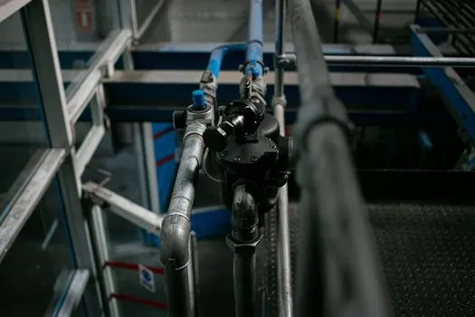
Thermodynamic traps use the energy in hot condensate and flashing steam to open and close the discharge device; disc, piston, and lever are listed as examples [S3].
Thermodynamic traps discharge intermittently, with flash steam forming above the disc and closing it until condensation reduces the control-chamber pressure [S4].
Mechanical traps are not universal replacements for thermodynamic traps. Their strong air-handling capability suits process equipment, but the selected float, bucket, piston, or lever mechanism must match the required capacity, installation orientation, and discharge condition [S3][S4].
Condensate load and discharge configuration drive sizing
The calculated condensate load must exceed the trap’s rated discharge capacity at the actual inlet pressure and outlet back pressure, and the manufacturer’s recommended safety factor must then be applied [S2].
Power-plant selection should distinguish hot condensate discharge from subcooled discharge because the trap must suit the heat content and flow pattern of the drainage [S2]. Steam distribution piping generally requires a trap designed for rapid, near-to-steam-temperature discharge to limit condensate pooling and water hammer [S2].
Steam-heated equipment also benefits from continuous condensate discharge, but a modulating control valve can reduce inlet pressure below the return-line back pressure and stall condensate flow. In that condition, a trap alone may not discharge reliably, and a higher-secondary-pressure pump-and-trap arrangement can be required [S2].
Where condensate must lift to a return line or into a pressurized system, the installation should be reviewed for water hammer, flooding, return-line sizing, and flash-steam overpressure [S5].
Where the mainstream disc trap should not be specified
Do not select a disc trap solely because the steam system is high pressure; a process drain with a large, fluctuating condensate load and substantial air-removal requirement may need a float, inverted-bucket, piston, or lever trap [S3].
Do not use a fixed trap to solve a stalled drainage condition. When the steam supply pressure falls below back pressure, a trap that cannot discharge under that condition will retain condensate, so a pump-assisted trap or separate condensate pump may be the correct arrangement [S2].
Do not assume a correct trap can compensate for poor pipework. Water hammer can result from condensate remaining in the path of high-velocity steam, an obstructed or undersized condensate return, flooding, or throttling of flash steam; persistent water-hammer failures require investigation of the system layout rather than repeated trap replacement [S5].
For sizing multipliers and selection logic, Steam Trap Safety Factor: Sizing Multiplier Rules and Selection Matrix provides a focused companion reference, while the final selection should still use the selected manufacturer’s certified capacity curves and stated safety factor [S2].
Materials, installation, and failure consequences
Body material must be checked against pressure, temperature, water chemistry, and contamination rather than copied from a similar utility service [S2][S3]. Dirt can interfere with trap operation, so condensate quality, boiler-treatment carryover, and strainer arrangements belong in the purchase specification [S3][S5].
Failed-open traps can discharge live steam, increasing steam-generation cost and emissions; failed-closed traps retain condensate, raising water hammer, impingement, corrosion, freezing, slip, and reliability risks [S3]. A trap that fails open can also degrade steam quality where process consistency depends on dry, uniform steam [S3].
Air and other non-condensable gases should be removed because they impede startup and heat transfer and can contribute to erosion and corrosion in steam lines [S4]. Mechanical traps often provide the air-handling advantage sought for process equipment, while thermodynamic traps are selected for compact, rugged high-pressure drainage [S3][S4].
Monitoring is an available design layer: Emerson describes steam traps with optional monitoring intended to help minimize steam loss [S1]. Monitoring supports condition verification but does not replace correct sizing, correct installation, or periodic testing; Emerson notes that steam traps are commonly tested once or twice per year and that a failed trap may remain unnoticed for more than six months [S3].
Specification and procurement workflow
A complete power-generation trap datasheet should state maximum operating pressure, design pressure, design temperature, operating temperature, inlet and outlet pressures, condensate load, trap type, body and trim materials, orientation, connection type, air-handling requirement, and whether a strainer or monitoring function is required [S2][S3].
The procurement sequence is: identify the application and required discharge character, select the applicable technology, obtain a model for the pressure, temperature, orientation, and installation conditions, calculate the load, apply the manufacturer’s recommended safety factor, and compare life-cycle cost among technically compliant options [S2].
Final model submittals should also include dimensional drawings, approved materials, installation orientation, capacity data at the specified inlet and outlet pressures, and available spare parts [S3]. For turbine-connected systems, confirm whether the drain requires zero-pressure discharge, elevated back pressure, lift assistance, or controlled drainage before approving a trap.
Trackable procurement signals are the completed inlet and outlet pressure basis in bar and psi, the design temperature in °C, the calculated load in kg/h or lb/h, and the manufacturer’s applied safety factor. These four entries allow a reviewer to reproduce the sizing calculation and reject an underspecified model [S2][S3].