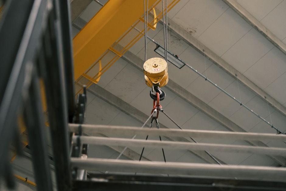
A 7-wire steel strand of nominal 12.7 mm (0.5 in.) or 15.2 mm (0.6 in.) diameter is the default tensile member in post-tensioned concrete, ground anchors, and overhead guy systems; correct duct placement, stressing sequence, and grout cover decide whether the assembly hits the rated 1860 MPa tensile strength or fails by corrosion within a decade [S3].
This guide covers the four installation tasks that drive 80 percent of field rework on strand-based systems: duct and sheathing layout, prestressing strand threading and seating, grout injection parameters, and the corrosion-protection decisions that govern whether a galvanized or unbonded strand assembly is the right spec [S3].
Duct, Sheathing and Concrete-Cover Geometry
Strand ducts for internal post-tensioning are commonly corrugated HDPE or galvanized metal with an internal cross-section at least 1.5x the net strand area to limit grout voids and friction losses during stressing [S3].
Minimum clear cover from duct outer wall to the nearest concrete face is typically 50 mm for slabs and 75-100 mm for bridge girders, driven by the bond requirements of the surrounding carbon steel reinforcement and by fire-resistance code call-outs rather than by the strand itself [S3]. Support chairs must hold the duct on a profile that does not deviate more than about 6 mm per metre from the design tendon centroid; greater sag produces unintended reverse curvature and high friction-loss spikes that the jack cannot recover [S3]. Sheathing joints are taped and, in aggressive environments, wrapped with heat-shrink sleeves to keep the alkaline grout from contacting the bare steel wires before injection [S3].
Strand Selection: Galvanized vs Unbonded vs Prestressed
Three strand families dominate the market, and the wrong pick is the single largest cause of early tendon replacement: hot-dip galvanized (zinc-coated) strand for guy wires, messenger wires, and exposed structural tension members; unbonded strand (factory-extruded PE sheath over greased wires) for slab post-tensioning where individual replacement is impractical; and bare prestressing strand for bonded tendons grouted inside a duct [S3].
Galvanized zinc coating mass on 7-wire strand is commonly specified in the 229-305 g/m² range for bridge stay cables and ground anchors, giving roughly 30-50 µm of zinc per side and a service life tied to atmospheric chloride exposure rather than to a calendar date [S3]. Unbonded strand is not a corrosion-protected system in the strict sense; the grease and PE sheath are a sliding-layer and a moisture barrier, and the strand should be rejected at the reel if the sheath shows UV chalking, cuts, or grease bleed-through [S3]. For aggressive or marine exposure, epoxy-coated or galvanized strand outperforms bare strand in accelerated salt-spray tests by an order of magnitude in time-to-first-red-rust, but epoxy cannot be bent around standard anchorage hardware without cracking, so the choice cascades into the stressing sequence [S3].
Stressing Sequence, Jack Calibration and Elongation Tolerance

Stressing is the operation that turns a passive bundle of wires into a structural prestressing strand; it is also the operation where most field acceptance disputes originate because elongation is the only number the inspector sees.
Field stressing usually targets 70-80 percent of the strand's nominal ultimate tensile strength (about 1300-1395 MPa for a 1860 MPa strand) to leave a 20-30 percent safety margin against the overstressing failure mode [S3]. Hydraulic jacks are paired with calibrated load cells or proving rings; the ram pressure-vs-force curve must be re-verified at least annually and after any seal replacement, with a typical accuracy band of ±2 percent of full scale [S3]. Elongation is predicted from the strand's elastic modulus (approximately 195 GPa for 7-wire prestressing strand), the free length between anchorages, and the assumed friction/ wobble coefficients (commonly µ = 0.15-0.25 and k = 0.001-0.003 per metre for greased and sheathed tendons in HDPE ducts) [S3]. Acceptance is usually the predicted elongation ±7 percent for bonded tendons, with any reading outside ±10 percent triggering a hold-point review of duct profile, jack calibration, and strand seating slip before the tendon is grouted [S3]. Seating slip behind the anchor wedges is typically 4-8 mm at transfer and is accounted for in the jack stroke; under-seating losses above 10 mm indicate contaminated wedges or a worn anchor cone and require re-anchoring [S3].
Grout Mix, Injection Pressure and Void Control
Grout is the corrosion barrier for bonded post-tensioning; the w/c ratio, bleed, and injection pressure decide whether the duct fills completely or leaves a water-collecting void that corrodes the strand from the inside.
Standard grout mixes use Type I/II Portland cement with a w/c ratio of about 0.40-0.45, a pozzolanic or thixotropic additive to limit bleed below 0.5 percent at 3 hours, and a fluidity cone time of 11-18 seconds so the mix flows around the strand bundle without segregating [S3]. Injection pressure is held at 0.3-1.0 MPa at the inlet for vertical tendons and not more than about 0.5 MPa for horizontal tendons to avoid rupturing the duct wall; grout must flow from the outlet until the consistency and colour match the inlet before the vent is closed, otherwise trapped air and bleed water remain inside the duct [S3]. For long or vertical tendons a vacuum-assisted grouting method pre-evacuates air from the duct and lets the grout fill under a smaller pressure differential, typically reducing voids in the high-point pockets of bridge girders [S3]. If the duct cannot be fully grouted at first attempt, the tendon should be re-flushed and re-stressed is not an option; the only corrective action is to drill and grout any remaining voids from the outside, which is why the embedded part TCO of a post-tensioned bridge is dominated by access, not by the carbon steel strand itself.
Common Failure Modes and When Not to Repair
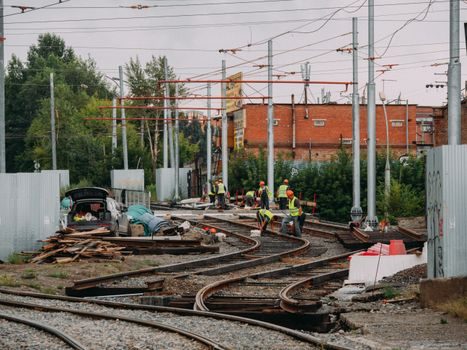
Four failure modes account for most strand replacement calls: broken wires at the anchorage, duct blockage, strand corrosion under insufficient grout cover, and overstressing cracks in the anchorage zone concrete.
Symptom-to-cause map: single wire breaks at the wedge usually mean seating slip from contaminated or undersized wedges — corrective action is re-anchoring with a verified wedge set; do not continue stressing. Blockage during grouting manifests as a stalled outlet flow or a sudden pressure rise — corrective action is flush, locate the blockage by tapping the duct, and drill an access port; do not increase pressure to force grout through. Strand corrosion shows as rust staining or section loss at anchorages or high points — corrective action is full tendon replacement rather than patching, because the corroded length is rarely localised. Concrete cracking behind anchorages above 0.2-0.3 mm width during transfer usually means the local bursting reinforcement is undersized — corrective action is to unload the tendon, redesign the anchorage zone, and re-stress only after the reinforcement is supplemented; further stressing on a cracked anchorage will split the concrete.
Acceptance Tests and Sourcing Signals
Acceptance for a strand installation is a four-part check: duct profile survey on the as-built geometry, jack calibration and elongation record, grouting record with inlet/outlet volumes and pressures, and a post-tensioning inspection that includes at least one pull-out or lift-off test on a representative tendon to confirm the in-service force [S3].
On the sourcing side, look for mill certificates that report diameter, cross-section, ultimate tensile strength, yield at 0.2 percent offset, elastic modulus, relaxation class (low-relaxation strand is typically ≤2.5 percent loss at 1000 hours), and zinc-coating mass where galvanized steel strand is specified; if the cert is missing any of those fields, treat the reel as unverified and quarantine it [S3]. For alloy steel anchorage hardware, require matching heat-traceable certificates because mixed heats in one anchorage zone are a known cause of uneven wedge seating. Trackable signals to watch in the next 6-12 months: revisions to grout-additive specifications following the latest post-tensioned-bridge durability studies, and any move by domestic mills to publish low-relaxation strand data sheets in metric and imperial units on the same page — both changes compress the field-engineering decision cycle for new strand installations.