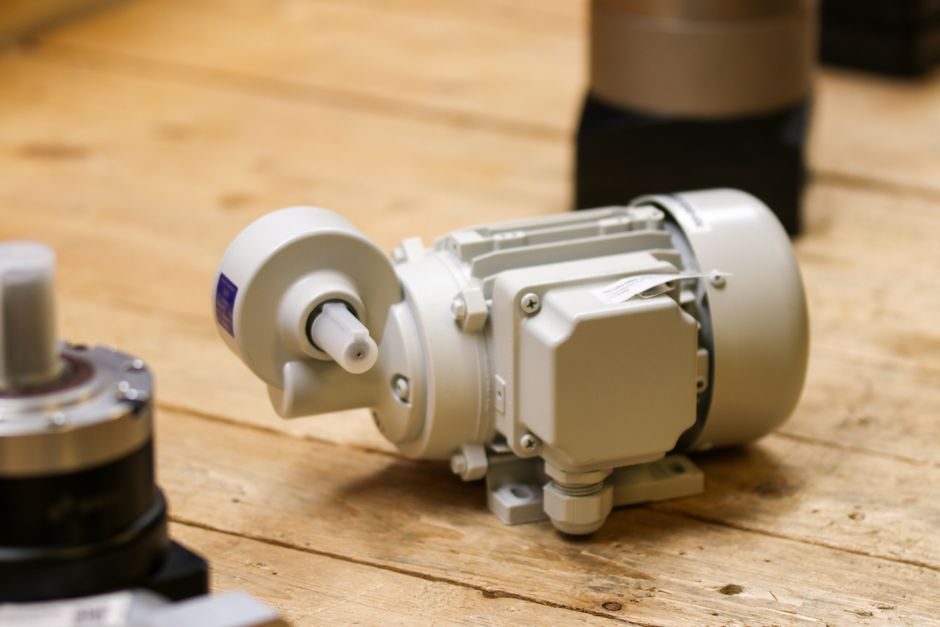
Stepper motors are DC electric machines that move in discrete angular steps via energized coil sets, with a permanent-magnet rotor and two stator windings driving whole-step, half-step, and microstep resolutions [S1][S6].
Practical selection is constrained by four hard numbers: NEMA frame (NEMA 8/11/14/17/23/34/42), rated holding torque (N·m or oz-in), step angle (commonly 1.8° / 200 steps/rev, or 0.9° / 400 steps/rev), and the matching bipolar or unipolar stepper drive topology [S1][S2].
NEMA Frame & Step Angle: Mechanical Fit First
Frame size dictates the maximum rotor diameter and thus the upper ceiling on holding torque — NEMA 17 typically delivers 0.4–0.7 N·m, NEMA 23 lands between 1.0–3.0 N·m, and NEMA 34/42 steppers reach 3.0–12 N·m and beyond in the high-torque POWERMAX II M and P Series [S2].
Step angle of 1.8° (200 steps/rev) is the dominant industrial pitch, with 0.9° (400 steps/rev) chosen where smoother low-speed motion or finer resolution is required without resorting to a mechanical gearbox [S1]. Frame and step angle together set the build envelope; selecting the larger frame before checking shaft load and bearing ratings is a common downstream rework cause.
Holding Torque vs Dynamic Torque: The Real Operating Window
Datasheet holding torque is measured at zero rpm with both phases energized, so it is a static ceiling — usable dynamic torque collapses as speed rises because back-EMF subtracts from the drive voltage headroom [S1][S2]. A motor rated 3 N·m holding may only deliver 1.0–1.5 N·m at 1,000 rpm on a 48 V supply, and 0.3 N·m at 2,000 rpm.
Use the published speed-torque curve, not the holding figure, to size against load torque plus 30–50% safety margin. For applications where load inertia exceeds 3× rotor inertia, add a damped coupling or downsize the step angle to keep resonance out of the operating band [S1].
Permanent Magnet vs Hybrid vs Variable Reluctance: Three Topologies, Three Profiles
Permanent-magnet (PM) steppers use a two-pole magnet rotor and run coarse step angles of 7.5° or 15°; they are low-cost, low-resolution, and common in instrumentation and small valves [S1][S6].
Hybrid steppers combine a magnetized, toothed rotor with toothed stator poles, giving fine 1.8°/0.9° steps and the strongest torque-per-frame ratio — this is what the POWERMAX II M and P Series uses, with optional modifications and global availability [S2]. Variable reluctance (VR) steppers have no magnet and rely purely on saliency, yielding high speed but low holding torque; they appear in instrumentation, not motion stages.
Selection rule: PM for low-cost OEM consumer gear, hybrid for 90% of positioning and indexing duties, VR only when high step rate exceeds what magnet saturation will allow. For variable-speed point-to-point profiling on the same platform used in industrial servo replacement work, the comparison against a brushless servo in servo motor selection: spec-based decision map is worth reading before committing.
Stepper Drive Pairing: Voltage, Current, and Microstepping
Bipolar chopper drives at 24–80 VDC are the standard pairing for NEMA 17/23/34 hybrid motors, with current set to the motor's rated phase current and microstepping configured at 1/8, 1/16, or 1/256 depending on resolution and smoothness targets [S1].
Raising supply voltage above the rated 12–24 V "printer" range to 48–80 V is the single most effective lever for extending usable torque above 1,000 rpm, because it overcomes back-EMF and lets the driver push current into the winding at speed [S2]. Open-loop control via Arduino libraries such as SpeedyStepper (active, 9 commits) and FlexyStepper (5 commits, in-motion speed changes) is fine for prototyping up to a few N·m; closed-loop steppers with integrated encoders are the right call when stall detection or position validation is required [S4][S5]. The stepper drive topology choice — constant-voltage, constant-current chopper, or closed-loop — must be locked in before motor selection, not after.
Who Should NOT Pick a Mainstream Open-Loop Stepper
Open-loop steppers lose position silently when a transient overload exceeds available torque — there is no feedback to flag a missed step. They are the wrong choice for: (a) vertical axes where a missed step means a falling load, (b) high-inertia loads whose inertia ratio exceeds roughly 3:1 without gearbox isolation, and (c) continuous high-speed operation above 1,500 rpm where resonance bands and torque droop dominate [S1].
For those cases, a closed-loop stepper with encoder feedback or a brushless servo on a linear guide stage is the engineering-correct pick. A typical capstone example using NEMA 34 with a microcontroller controller board is documented at the UPCeramicKnee/motor-controller repository, illustrating exactly the open-loop risk profile at 3+ N·m loads [S3].
Thermal, Duty Cycle & Certification Constraints
Stepper motors heat up because they consume power while holding position — a 3 N·m motor holding 100% current can reach 80–100 °C without a thermal cutout, derating winding life. Spec the motor with a 50% duty cycle margin if the application holds position for more than 30 seconds, or add forced-air cooling [S1][S2].
Certifications matter for machinery going into CE-marked or UL-listed end products. The POWERMAX II M and P Series is built to UL and CE requirements with global availability, which is a hard filter for OEM buyers shipping into regulated markets [S2].
Shortlist Logic: From Requirement to One Motor
Convert the load into four numbers — required holding torque, peak speed, step resolution, and available supply voltage — then match frame size (NEMA 17/23/34), step angle (1.8°/0.9°), and drive topology (chopper vs closed-loop) to those numbers with a 30–50% margin on torque [S1][S2].
Watch the supply-voltage headroom for high-speed duty, derate for thermal load, and pick open-loop only when stall cost is acceptable; otherwise escalate to closed-loop stepper or brushless servo. Two trackable signals to confirm fit on the next BOM review: (1) the published speed-torque curve at your actual supply voltage, not a generic curve, and (2) the rotor-to-load inertia ratio held below 3:1 or gearbox-isolated.
Component reference pages worth checking: stepper motor.