
A rack-mounted PLC is a chassis-based controller where the CPU, power supply, digital and analog I/O, communication modules, and optional safety CPU plug into a common backplane inside a 19-inch EIA rack, as distinct from compact or modular brick PLCs where the CPU and I/O live in one housing. Selection starts with the backplane — slot count, I/O addressing depth, and hot-swap capability — because every downstream cost (CPU upgrade, I/O expansion, cabinet space) traces back to that frame.
Three numbers frame every rack-PLC decision: the EIA footprint the chassis occupies (typically 3U to 9U), the maximum I/O points the backplane can address, and the scan-time class the application demands. The mechanical and electrical prerequisites for any rack-mounted industrial controller mirror server-grade hardware installation practice: a Phillips screwdriver, flat-head screwdriver, box cutter, and an ESD wrist strap are the minimum toolkit, with a rack providing the EIA-spaced mounting holes the chassis bolts into [S1].
Backplane Architecture and Slot Budget
Rack PLCs separate the CPU from the I/O — every module sits on a common backplane that carries the data, address, and power rails, and the chassis defines the hard ceiling on system scale. Slot count for a mid-size rack PLC lands in the 8- to 16-slot range; large-process chassis run to 24 slots with expansion racks daisy-chained for higher counts, while compact rack frames used in machine-level cells sit at 4-8 slots. [S2]
The dominant backplane interconnect on modern rack PLCs is a parallel proprietary bus (vendor-locked), increasingly overlaid with Ethernet-based backplanes for high-speed peer-to-peer traffic between CPUs and intelligent I/O. A practical rule: budget one slot per 16 digital inputs OR 16 digital outputs, one slot per 8 analog channels, and reserve a slot for the power supply and a slot for the CPU. A 16-slot frame therefore typically absorbs 1 CPU + 1 PSU + ~14 I/O slots before any expansion rack is added.
Selection must distinguish addressable I/O (the backplane's theoretical maximum, often several thousand points) from installed I/O (what the slot count and module density actually hold) — engineering effort should size the chassis for 20-30% spare slots so future I/O additions do not require a chassis swap. Rack PLCs are the right answer when the application exceeds roughly 256 I/O or needs mixed analog, high-speed counter, motion, and safety modules in one frame; below that threshold, a modular PLC brick costs less per point and fits in a smaller cabinet.
CPU Class, Scan Time, and Program Memory
The CPU module sets the scan-time floor: small rack CPUs execute a 1K-instruction boolean scan in the 0.1-1 ms range, mid-range CPUs in the 0.05-0.2 ms range, and high-end process CPUs in the sub-0.05 ms range. Scan time is the binding constraint for high-speed packaging, motion coordination, and safety integration — a 0.1 ms scan supports deterministic 1 kHz motion loops, while a 1 ms scan is borderline for multi-axis servo control.
Program memory and data memory scale by an order of magnitude across CPU classes — entry rack CPUs carry tens of kilobytes of program memory, mid-range units megabytes, and high-end process CPUs tens of megabytes with optional extended memory cards. Selection should not chase the highest scan time as a default; overspec'd CPU costs 2-4x the price for a duty cycle the backplane I/O never demands. The cost/benefit crossover is roughly at 1 ms scan / 512 KB program memory — below that, a compact PLC suffices; above, a rack CPU pays back in panel space and scan determinism.
Redundant CPU configurations (two CPUs in hot-standby, automatic switchover under one scan) are a rack-PLC-only option, supported on the high-end process tier and used in continuous-process plants where a CPU fault must not stop the line. For most machine-level and skid-mounted applications, a single CPU with a watch-dog relay and a safety PLC covers the reliability requirement at lower cost. Reference architecture for total cost of ownership across modular versus rack PLCs is detailed in the modular PLC price and cost guide.
I/O Density, Module Type Mix, and Field Wiring
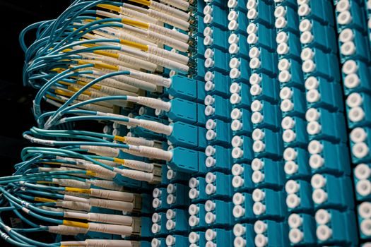
Module selection in a rack PLC is per-slot and is constrained by the backplane's voltage classes and isolation ratings. Digital input modules typically handle 24 VDC or 120/230 VAC at 8, 16, or 32 channels per module; digital outputs come in transistor (DC, switching faster, longer life) and relay (AC/DC, lower cost, slower) variants at 8, 16, or 32 channels. Analog I/O modules commonly deliver 4, 8, or 16 channels of voltage (0-10 V, ±10 V) or current (4-20 mA) input, with isolated and non-isolated versions that differ by 30-50% in price.
High-density 32-channel modules shrink slot count but force smaller wiring terminals (often 1.5 mm² or 2.5 mm² maximum) and limit per-channel fusing; a 16-channel module is the practical density ceiling for 24 VDC discrete wiring where each channel is fused. Analog modules should be chosen by signal type first (4-20 mA is the field-bus default for instrumentation), isolation second (channel-to-channel isolation needed for thermocouple and bridge inputs, channel-to-backplane is sufficient for most 4-20 mA), and resolution last (12-14 bits adequate for general process, 16-bit required for lab and metrology). Mixing high-density digital with low-density analog in the same rack is normal and is the structure the backplane is designed to support.
Safety PLC Integration and Safety I/O
A safety PLC is a separate CPU and I/O subsystem that runs certified safety logic — emergency stop, light curtain, guard door, two-hand control, and safety-rated analog shutdown — to a defined Performance Level (PL) per ISO 13849-1 or Safety Integrity Level (SIL) per IEC 61508. In a rack-PLC architecture the safety CPU is a second processor module in the same chassis OR a standalone safety PLC on a dedicated backplane that shares only the field wiring and a safe communication link with the standard CPU.
Selection hinges on the safety integrity level the application demands: SIL 1/PLa covers basic E-stop and guard interlock, SIL 2/PLd covers most machine safety functions, and SIL 3/PLe covers high-hazard process and robotic cells where a single fault cannot cause loss of the safety function. A safety CPU module typically carries a dual-core lockstep processor, certified to IEC 61508 SIL 3 at the module level, and uses safety-rated digital I/O with built-in line monitoring (pulse testing) to detect short circuits and wire breaks. Cost premium for the safety CPU and its I/O over a non-safety equivalent is 2-3x at the module level; the bigger cost driver is the application-engineering hours to map each safety function to its required PL or SIL.
For users who already run a non-safety rack PLC and only need SIL 2/Pld on a few machine cells, a separate compact safety PLC wired to the main rack's standard I/O is often more economical than a second safety CPU module in the main rack. The safety PLC is not for users with a SIL 3 process loop where the field instruments are themselves safety-rated; in that duty, the safety function must be designed into the loop, not bolted on at the controller. Reference: safety PLC architecture and selection criteria.
Communication, Fieldbus, and Industrial Ethernet
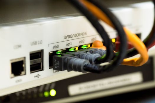
Rack PLCs carry their communication modules as plug-in cards on the backplane: serial (RS-232, RS-485) for legacy device and Modbus RTU links, dedicated fieldbus cards for PROFIBUS, FOUNDATION Fieldbus, or DeviceNet, and Industrial Ethernet modules for PROFINET, EtherNet/IP, and Modbus TCP. The selection criterion is the mix of devices on the floor — a brownfield plant with PROFIBUS DP slaves needs at least one PROFIBUS master module; a greenfield machine with servo drives wants PROFINET or EtherNet/IP at 100 Mbit/s full duplex with IRT or CIP Sync for determinism. [S3]
Ethernet-based backplanes increasingly carry a mix of standard TCP/IP traffic (HMI, MES, historian) and real-time control traffic on the same physical cable, separated by VLAN and QoS settings — a correctly configured managed switch on the cell network is the difference between a 1 ms and a 50 ms effective scan. Wireless modules (WLAN, Bluetooth, or 5G) appear in modern rack PLCs for mobile HMI, asset tracker integration, and remote I/O panels where cable runs are impractical, and follow the same certification logic (radio approvals per country) as any industrial radio. Rack-PLC selection should plan for one communication slot per 20-30 slaves on the fieldbus, plus a dedicated slot for the plant Ethernet uplink.
Power Supply, Grounding, and Environmental Envelope
The rack-PLC power supply module converts 120/230 VAC or 24 VDC field power to the backplane's DC bus (commonly 5 VDC logic, 24 VDC for I/O) and is sized in watts by the sum of the modules' backplane current draw plus a 25-50% margin. A 16-slot rack with one CPU, one communication module, and 14 I/O modules typically draws 60-120 W from the supply — a 150 W supply gives the headroom for two extra I/O modules on a future expansion. [S2]
Conformal coating of the I/O modules is the differentiator for plants with condensing humidity, corrosive atmosphere, or outdoor cabinets — uncoated modules fail within months under H2S or Cl2 exposure that a coated module survives for years. Redundant power supply modules (two supplies in parallel, one load-sharing, one standby) are a rack-PLC-only option used where a supply fault cannot stop the process; mid-size plants rarely justify the cost.
Selection Criteria Matrix: Compact vs Modular vs Rack PLC
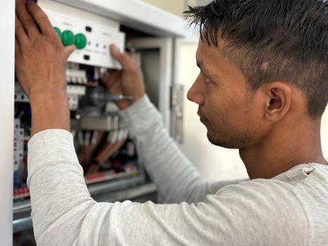
The three PLC form factors are not interchangeable. A compact PLC (CPU + I/O in one housing) fits 16-64 I/O points and small machine control; a modular PLC (CPU + stackable I/O modules on a side bus) fits 64-512 I/O with limited mix-and-match; a rack PLC (CPU + I/O on a backplane inside an EIA chassis) fits 256-10,000+ I/O with full module and redundancy options. The cost-per-I/O-point crossover sits at roughly 256 points — below that the modular brick wins, above that the rack chassis wins because slot density and shared power scale better. [S1]
For an OEM building a packaging machine that will be replicated 50 times, the modular PLC gives the lowest unit cost. For a process plant running a reactor, tank farm, and 2000 I/O on continuous duty, the rack PLC is the only form factor that supports redundant CPU, redundant PSU, and a mix of high-speed, analog, and safety modules in one frame. For a skid with 64 I/O and a single E-stop loop, a compact PLC with a small remote safety module is the correct answer — a rack PLC would be 5-10x the panel cost for no functional gain. Reference architecture for this decision tree is detailed in the PLC selection and architecture overview.
Who Should NOT Pick a Rack PLC
Rack PLCs are the wrong form factor for low-I/O, low-complexity machines. A machine with 32 I/O, a single CPU, and one HMI does not need a 19-inch chassis — the modular PLC delivers the same functionality at 30-50% of the cabinet cost and 40% of the panel space. Small skid builders, OEM machine builders shipping under 100 units per year, and any application under 256 I/O are the user groups where rack PLCs consistently lose on cost.
Rack PLCs are also the wrong choice for plant-floor areas without a 19-inch EIA rack or cabinet. The chassis requires bolted mounting to EIA-spaced rails, with the cooling airflow path defined by the cabinet's fan and filter layout — a wall-mount enclosure without those features needs rework before a rack PLC will install cleanly. Applications with extreme vibration (mobile equipment, large compressors) need a vibration-isolated sub-panel inside the cabinet; an off-the-shelf rack PLC bolted direct to a vibrating skid will fail connector and backplane solder joints within months. Plants in corrosive atmospheres (coastal, chemical, paper) need conformal-coated I/O modules and IP65 cabinet seals; neither is optional in those environments.
Shortlist Logic and Next Decision Node
The vendors' chassis families then resolve the long-list to a 2-3 model comparison; bench-test the candidate CPUs against the application's worst-case scan time and program size before locking the BOM. Trackable signals at the next decision node are the cabinet-cooling budget (rack-mounted cooling is now a separately specified subsystem, with vendors launching dedicated rack-internal cooling for high-density PLC and server frames [S2]) and the safety-PLC integration mode (shared backplane vs standalone chassis vs remote I/O link).
Spec-level background on the components involved: linear guide.