A bonded foil strain gauge typically converts a microstrain of 1–2 µε into a millivolt-level bridge output, while a non-contact laser displacement sensor delivers a calibrated millimetre or micron position reading from 0–600 bar-class machines down to PCB flex testing [S1][S2].
The two technologies are routinely confused because they both appear in test rigs, on press frames, and in OEM QA fixtures, but the physical quantity, the output signal chain, and the calibration discipline are different. This map lines them up by sensing principle, full-scale range, output, environment, and integration effort so a process engineer can pick in under five minutes.
Sensing Principle and What Each Device Actually Measures
A strain gauge measures the fractional change in length (ε = ΔL/L) of a conductor bonded to the test article, which is then resolved through a Wheatstone bridge into voltage. The reference BF350-3AA cell carries a constantan grid of 3 × 3 mm on a 6 × 4.5 mm phenolic substrate, gauge factor 2.0 ± tolerance, 350 Ω bridge resistance, strain limit 2%, fatigue life > 10,000,000 cycles [S2].
A displacement sensor measures linear position change of a target relative to a fixed reference, with output in mm, µm, or engineering units. Optical/laser variants (triangulation, confocal, spectral) are non-contact; LVDT and draw-wire variants are contact. Both classes are complementary to the strain gauge: strain answers "how stressed is the part," displacement answers "how far has it moved."
Range, Resolution, and Bandwidth Comparison
Bonded foil gauges resolve sub-µε; the BF350-3AA datasheet cites a minimum resolvable strain of 1–2 µε with non-linearity below 1%, and a measurable range that spans elastic strain up to plastic strain of 1–2%, extending to 20% on special-pattern gauges [S2][S3]. Bandwidth is set by the bridge excitation and the amplifier, commonly DC to 100 kHz for static and dynamic strain.
Displacement sensors split by technology: a triangulation laser displacement sensor typically delivers 0.1–0.5 µm resolution over 10–200 mm stand-off; a confocal displacement sensor covers 0.5–30 mm range with sub-nanometre resolution for transparent and polished targets. LVDT sensors cover millimetres to several hundred millimetres with sub-µm repeatability. The crossover where a strain gauge becomes the wrong tool is roughly above 1–2% strain on a part; above that you are usually integrating strain to displacement and accumulating error.
Mounting, Environment, and Signal Conditioning
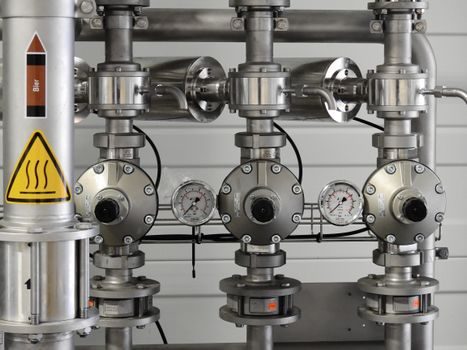
Strain gauge installation is the dominant source of measurement error. The TSK / Kyowa KFG-1-350-D17-11N30C2 family covered by the Chinese distributor catalogue requires surface preparation, adhesive selection (cyanoacrylate for room temperature, epoxy for -269 °C to +800 °C service per Kyowa's published self-compensated gauge range [S3]), bridge completion, lead-wire compensation (3-wire or Kelvin), and temperature self-compensation matched to the substrate material.
Displacement sensors are typically clamp-mounted or fixture-mounted; laser triangulation needs a clear optical path, controlled surface finish (matte for diffuse, specular for triangulation), and standoff within the published focal range. LVDT and draw-wire sensors tolerate dust, oil, and water; laser units need IP65 or better enclosures and clean air curtains in dirty process cells.
Decision Matrix: Strain Gauge vs Displacement Sensor
For structural stress on a fixed part under load: pick a strain gauge. It is the only practical tool for sub-µε resolution on a load-bearing member, and the only one that survives embedded installation inside a composite layup or a concrete pour. The BF350-3AA 350 Ω constantan grid is the de-facto commodity cell in this role [S2].
For travel, run-out, position control, or thickness profiling on a moving or accessible target: pick a displacement sensor. A laser triangulation unit is correct for hot-rolling strip and cylinder bore inspection; a confocal displacement sensor is correct for glass, film, and lens thickness where the target is transparent; an LVDT is correct for hydraulic cylinder stroke in dirty, oily, or submerged service. Strain gauges are the wrong tool for these because the integration of strain over a moving target path adds noise and drift that a direct position reading avoids.
Integration Effort, Cost, and Calibration Discipline
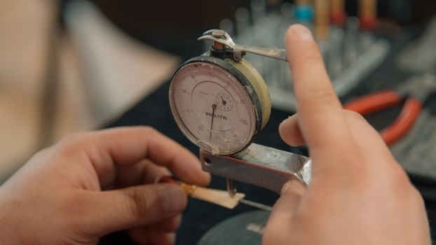
Strain gauge integration is labour-heavy. Each gauge needs surface prep, adhesive cure, bridge wiring, shunt calibration, lead compensation, and temperature compensation — a single-channel load-cell-grade install is typically 2–4 hours of technician time plus a known shunt resistor and a temperature soak. The cell itself is cheap: a BF350-3AA lot is priced in single-digit USD per piece at industrial quantities [S2], and full-bridge assemblies from Suzhou distributors show ¥1 reference pricing for low-end stress-test sensors [S3].
Displacement sensors are plug-and-play by comparison: mount, route a 4–20 mA or IO-Link cable, set the analog scaling, and the device is in service. Industrial laser triangulation heads sit in the low-hundreds to low-thousands USD; confocal chromatic heads for transparent targets are typically 5–10× that. Calibration is a one-time span-and-zero against a traceable target; strain-gauge calibration is per-channel and per-mounting.
Failure Modes, Limitations, and Cross-Checking
Strain gauge failure modes: lead break, gauge lift, moisture ingress, zero drift with temperature, and zero shift after first load cycle. Mitigation is mechanical (encapsulation, lead strain relief), electrical (3-wire or 4-wire Kelvin), and procedural (post-install load verification, periodic shunt check). Published accuracy is below 1% only with proper installation; field data without compensation can be 5–10% off [S3].
Displacement sensor failure modes: target reflectivity change (laser triangulation), temperature-induced range shift, optical path obstruction, and for LVDT, core wear and bearing failure. The standard cross-check is to instrument one test article with both a strain gauge pair and a displacement sensor, integrate the strain to displacement over a known load, and reconcile to the displacement sensor reading — agreement within a few per cent confirms both channels.
Standards, Sourcing, and Real Sourcing Channels
Strain gauge selection is guided by vendor datasheets and the ASME / ISA / ISO 376 force-measurement conventions; the BF350-3AA and KFG-1-350-D17 families are documented with gauge factor, thermal output, and fatigue data on the manufacturer's page [S2][S3]. Displacement sensor selection follows the application class (laser safety class 2 or 3R, IP rating, CE/RED) and the metrology traceability path to national standards through ISO 9001 / ISO 17025 calibration labs.
For sourcing in 2026, the dominant channels are still direct-from-OEM for high-end Kyowa, HBM, and Kistler cells, and a layer of distributors in Suzhou, Shenzhen, and Deyang for commodity BF350 and TSK-pattern gauges [S3]. A similar two-tier pattern exists for displacement sensors: OEM direct for Keyence, Micro-Epsilon, and Acuity; regional distributor for the long tail. Track the next procurement round as the leading signal: every gauge or sensor family added to the approved-vendor list is a trackable indicator of which technology a plant is consolidating on.
See also our earlier report, Industrial Oven Types and Applications: A 2026 Spec-Driven Selection Map.