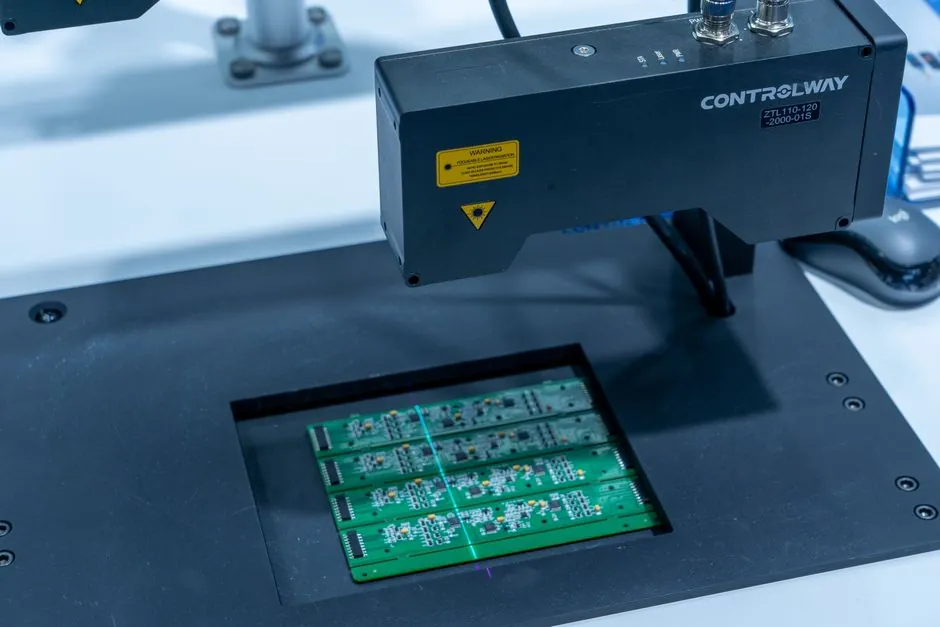
A structured light scanner is a specific implementation of an optical 3D scanner that projects a sequence of coded patterns (gray-code or sinusoidal fringe) and decodes them with one or more cameras, recovering XYZ by triangulation against the known projector geometry [S2][S3]. The generic term "3D scanner" instead includes laser line triangulation, time-of-flight, photogrammetry, SLAM LiDAR, and CT, each with different physics, working volume, and accuracy profile.
Buyers in 2026 are not asking "what is a 3D scanner" but "which sub-method fits my part size, surface, and shop-floor conditions" [S4]. Recent open-source releases (Triangulum3D, neuvision, feiran-l/Structured-light-stereo) explicitly target cheap projector + camera builds, while commercial SLAM and structured-light handheld units are pushing into artifact and cultural-heritage digitization [S4][S5].
Definition and Scope: What "Structured Light" Actually Means
Structured light scanning (SLS) projects a known illumination pattern (binary gray-code stripes or phase-shifted sinusoidal fringes) onto the target surface, then decodes each pixel by matching the pattern index to a known projector column, and finally triangulates that pixel against camera rays [S2][S6]. A working SLS rig is therefore three subsystems: a calibrated projector, one or two cameras with known intrinsics and extrinsics, and a decoder that turns N pattern images into a disparity map and point cloud [S3][S6].
The generic "3D scanner" label, by contrast, groups every non-contact ranging method: laser line triangulation (single laser stripe, sub-pixel peak detection), time-of-flight (phase or pulse, typical range 0.1–100 m), photogrammetry (passive, multi-view stereo from texture alone), and SLAM LiDAR (rotating or solid-state laser with simultaneous localization) [S3][S4]. Structured light is one of the most accurate optical sub-methods at working volumes below roughly 1 m, but its accuracy falls off with projector defocus, ambient IR/visible light, and specular or transparent surfaces [S2][S6].
Selection Criteria: Working Volume, Surface Type, and Motion
Working volume is the first hard filter. Structured light rigs calibrated at 300–800 mm standoff can return point density on the order of 10^5–10^6 points per scan with sub-0.1 mm RMS noise on matte surfaces [S3][S6]. Laser triangulation reaches comparable accuracy at single-line mode but at lower per-frame density; time-of-flight and SLAM LiDAR deliver millimeters-to-centimeters accuracy but at ranges of meters to tens of meters [S3][S4].
Surface response is the second filter. Structured light fails on mirror-finish metal, transparent glass, and highly absorptive black plastic, because the decoder relies on the camera seeing the projected pattern [S2][S5]. Laser triangulation tolerates darker surfaces better when the laser wavelength is chosen to match the material band (e.g. 660 nm red on plastics, 405 nm blue on metals), and SLAM LiDAR is largely immune to surface color as long as the return amplitude clears the receiver threshold [S4].
Motion and lighting are the third filter. Static, controlled-light booths favor structured light, because every pattern frame is taken with the part stationary [S3][S5]. Handheld or in-situ use favors SLAM or laser line triangulation, since the projector-camera baseline of an SLS rig is sensitive to vibration between pattern frames [S2][S4]. The triangulation math itself is published as standard stereo geometry: given two cameras plus a projector, the algorithm decodes a gray-code pattern, cleans invalid pixels, estimates projected-plane parameters, and computes per-pixel 3D ray intersections [S6].
Comparison: Sub-Methods on the Four Decision Criteria
Across the four criteria that drive purchasing, the four main sub-methods rank as follows. Working volume: structured light and laser triangulation are sub-1 m close-range; ToF and SLAM LiDAR are 1–100 m mid- to long-range [S3][S4]. Surface fidelity (matte, textured parts): structured light leads with 0.05–0.2 mm typical accuracy on a 300 mm part; laser triangulation is close behind at 0.02–0.1 mm but in single stripes; ToF and SLAM LiDAR drop to 1–10 mm [S3][S6]. Robustness to ambient light and vibration: SLAM LiDAR first, structured light worst (needs dark or controlled light) [S2][S4]. Cost and entry barrier: structured light has the lowest commercial entry point thanks to projector + webcam DIY builds, while industrial laser line and SLAM units sit 5–20x higher in capital cost [S1][S3][S4].
For a buyer comparing two products on a single line item, the decision often reduces to one question: is the part stationary and matte, and is the booth light-controlled? If yes, structured light wins on resolution per dollar; if no, switch to laser triangulation or SLAM LiDAR [S2][S4]. The same logic is summarized in the spec-first decision map for 3D scanner selection in 2026, which ranks working volume and surface type above brand or sensor count [3d-scanner-selection-criteria].
Use Cases That Map Cleanly to Each Method
Structured light is the default for desktop QC of small injection-molded or CNC-machined parts, dental and orthodontic model capture, and cultural-heritage digitization where the object is placed on a turntable and lit in a tent [S3][S4]. Open-source stacks such as neuvision (C++/Qt, OpenCV 4.2.x+, PCL 1.10.x+) and Triangulum3D (Python) target exactly this 200–600 mm working volume and report working builds on Basler, AVT/Allied Vision GigE cameras, and any OpenCV-compatible webcam [S3][S5].
Laser line triangulation is the workhorse for inline production metrology of larger cast or stamped parts, where the part moves on a conveyor and a fixed laser + line-scan camera pair produces cross-sectional profiles at kHz rates [S3]. Time-of-flight and SLAM LiDAR dominate reverse engineering of vehicles, building interiors, and outdoor sites, because they tolerate ambient light and can rebuild geometry while the sensor is moving through the space [S4]. Photogrammetry (passive multi-view) is still preferred for high-texture objects captured by a regular DSLR rig, since it needs no projector and scales to large monuments, but it collapses on textureless or shiny surfaces [S4].
Open-Source Pipelines in 2026: What You Can Build for Under a Projector
The 2026 open-source baseline is a 1-projector + 1 or 2-camera rig, with gray-code or binary-stripe decoding, epipolar geometry, and PCL-based point cloud post-processing [S2][S3][S6]. The nizvoo/3d-scanner repo is the minimal Python reference (GNU Make, GCC, Python 3.x, single webcam, single projector) and is the most-cited entry point for hobby builds [S1]. The feiran-l/Structured-light-stereo repo goes one step further with a true stereo camera + projector setup and includes a gray-code decoder that emits both disparity maps and triangulated point clouds, last touched in early 2024 and still widely forked [S2]. The neuvision framework is the most feature-complete: C++17, CMake, Qt 5.15+, OpenCV 4.2.x+, PCL 1.10.x+, tested on Windows, macOS, and Linux, with a calibration wizard for the single-camera + single-projector case [S3].
Two 2025–2026 additions push DIY further. Triangulum3D (2026-07-12) is a Python package that wraps a binary-encoded stripe projector and a calibration routine suitable for a desk-side lab [S5]. The maximm8/structured-light-scanner (2026-06-11) repo publishes a complete multi-camera structured-light implementation in Python using two monochrome cameras and one projector, with explicit handling of gray-code decoding, invalid-pixel cleanup, projected-plane parameter estimation, and per-pixel ray intersection [S6]. Together these repositories mean a 2026 buyer can prototype a working structured-light rig with a $300 projector, two $100 industrial cameras, and open-source code, and validate the method before paying for a commercial unit [S1][S3][S5][S6].
Standards, Sourcing, and Failure Modes to Watch
A structured-light scan should be evaluated on the same artifact the buyer will measure in production, and the report should specify working distance, lateral resolution, and point-to-point noise, not just a single "accuracy" number [S3][S6].
Failure modes are consistent across the open-source literature. Specular highlights and inter-reflections corrupt the gray-code decode, because the camera sees pattern positions shifted by the secondary reflection [S2][S5]. Projector defocus above roughly 1.5x the calibrated throw distance blurs stripe edges and reduces effective resolution [S6]. Vibration between pattern frames is a single hard error: even sub-millimeter movement mis-registers the N-th frame and the entire scan must be retaken [S2][S3]. On the laser-triangulation side, the dominant failure is laser speckle on shiny metals and saturation on white or retroreflective surfaces, which forces wavelength and exposure tuning per material [S3]. For field use, a wider decision context including machine-vision cameras and lighting design is covered in the spec-driven selection of smart camera vs machine vision systems [smart-camera-vs-machine-vision].
Trackable signals for the rest of 2026: the open-source repos above are adding calibration wizards and multi-projector support, while commercial SLAM units (Artec 3D and peers) are publishing cultural-heritage datasets with sub-millimeter structured-light scans of museum artifacts [S4]. A reasonable procurement plan is to spec accuracy on a 200 mm artifact, benchmark two open-source pipelines (Triangulum3D and maximm8) against a paid demo, and lock the supplier only after that benchmark on a real part.
Spec-level background on the components involved: industrial barcode scanner.
Related analysis: Smart Camera vs Machine Vision System: Spec-Driven Selection.