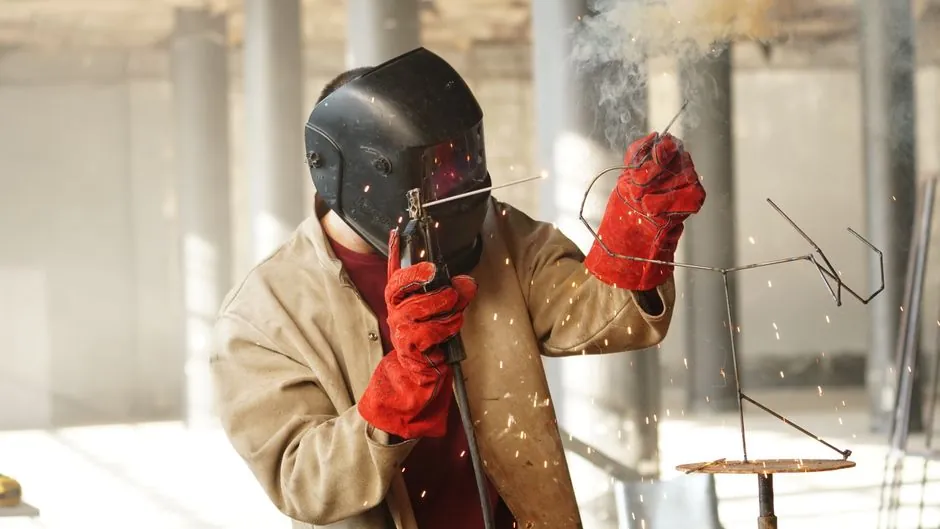
On bridge steel erection sites, stud welding is the default process for attaching headed shear connectors, anchor studs, and sign-support base plates to girder flanges, and the choice narrows to two machine families: capacitor-discharge (CD) stud welders for small-diameter fasteners (typically 3–10 mm) and drawn-arc (DA) stud welders for the 10–25 mm shear studs that dominate composite deck construction [S1].
Mabey Bridge's modular steel bridging programmes illustrate why stud welding is integral to accelerated bridge builds: pre-engineered components are joined on-site under tight shift cycles, and welded shear studs on launched girders must be ready for deck concrete placement within the same mobilisation window [S1]. The two technologies, however, solve different fastening problems and are not interchangeable on a single stud diameter.
Process family map: CD stud welding vs drawn-arc stud welding
CD stud welders (also called capacitor-discharge or contact stud welders) store energy in a capacitor bank and discharge it through the stud in 1–3 ms, fusing the stud to the base metal without a ceramic ferrule and without an arc-shielding gas. They are specified for thin-sheet fastening, insulation pins, and small-diameter fasteners, with typical stud diameters running 3–10 mm on mild steel and stainless base metals. The lack of a ferrule means the process leaves a clean, paintable fillet on the stud base, which is the reason CD is preferred where post-weld coating or galvanising touch-up is required [S1].
The ferrule contains the arc, shields the molten metal, and forms the weld fillet; it is broken off after welding. DA is the mandatory process for headed shear studs in composite bridge decks because it delivers the load-bearing weld area required by the AWS D1.5 Bridge Welding Code shear-connector tables [S1]. Typical stud diameters in bridge work are 12, 16, 19, 22, and 25 mm, with weld times of 0.2–1.2 s depending on diameter and current.
Decision criteria: stud diameter, base-metal thickness, and duty cycle
Stud diameter is the first gate. AWS D1.5 shear-connector diameters commonly specified for bridge girders fall in the 12–25 mm range, and that range is the territory of DA stud welders; CD units simply cannot deliver the weld cross-section for 16 mm and larger studs at code-compliant strength levels [S1].
Base-metal thickness is the second gate. AWS D1.5 requires that the base metal under a stud weld be of sufficient thickness to absorb the heat input without burn-through; for typical 12–19 mm shear studs on bridge girder flanges, this means a minimum flange thickness in the 9.5–12.7 mm range depending on stud size. CD welders, with their millisecond discharge, can attach 3–6 mm studs to sheet as thin as 0.6 mm, which is why they coexist with DA on a single bridge site for tasks like sign and lighting brackets.
Duty cycle and power source is the third gate. CD stud welders are rated in microfarads (capacitance), commonly 50,000–100,000 µF for the 3–8 mm range, and they are far lighter (often 5–15 kg portable) compared with a 90–150 kg DA power source. On bridge sites with limited crane access for the deck, the CD unit's portability is decisive for handrail and bracket work; the DA unit stays on the girder line under the stud-welding gun boom [S1].
Comparison table: CD stud welder vs DA stud welder on four selection criteria
Lining the two options against the four criteria that drive bridge-site purchase or rental decisions:
1) Stud diameter: CD handles 3–10 mm, DA handles 10–25 mm. For bridge shear studs (16–22 mm typical), only DA qualifies.
2) Weld strength vs base metal: CD produces a partial-penetration fusion suitable for light-duty fastening; DA produces a full cross-section weld qualified to AWS D1.5 shear-connector requirements for composite action.
3) Site footprint: CD portable units 5–15 kg, single-operator; DA systems 90–150 kg power source plus stud gun, ferrule dispenser, often crane-handled.
4) Post-weld finishing: CD leaves minimal fillet, no ferrule slag, paint-friendly; DA leaves a ferrule collar that must be chipped off and a fillet that may need grinding before coating. Reference data on duty cycles, stud diameter ranges, and ferrule behaviour cross-checks with general stud welder process descriptions.
Applicable standards and what they actually require
AWS D1.5M/D1.5 Bridge Welding Code is the governing document for stud welding on steel bridges in the US and is adopted or referenced in many international bridge specs. It covers stud base qualification, production welding, and pre-production testing, and it is the standard that defines the ferrule-arc-shielded drawn-arc process as the default for shear connectors [S1].
AWS C5.4 covers the recommended practices for stud welding more broadly, including CD, and is commonly referenced alongside D1.5 on the same project so that the small-diameter stud work (signs, luminaires, utility supports) and the shear-connector work both sit under named codes. On European projects, EN ISO 14555 is the equivalent stud-welding standard, and EN 1090-2 governs the execution of welded structures including bridges; both sit above the OEM machine selection.
On-site workflow: from pre-production testing to production welding
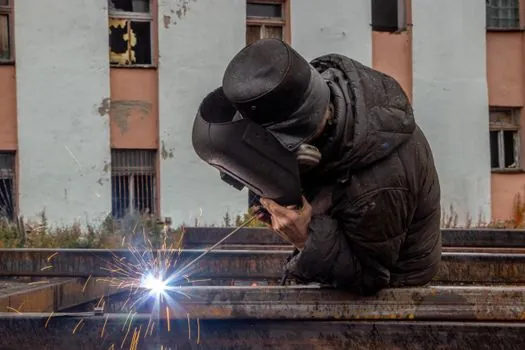
Before any production stud is welded on a bridge girder, AWS D1.5 requires a pre-production test: a set of studs is welded to a sample of the same base-metal grade and thickness, then bend-tested to 30 degrees or tension-tested to verify the procedure and the stud-gun settings. The bend test is the field shortcut, and a passing stud shows the bend ductility of the base metal, not the weld, which is the visual confirmation that the arc time, current, and lift were correct for that stud diameter.
In production, the deck-side sequence is consistent across modular bridge projects: surface cleaning by disc grinder to bright metal, gun set-down on the marked stud location, lift and arc initiation, plunge, and hold for the cool time prescribed by the stud manufacturer (typically 0.5–2 s for 16–22 mm studs). The stud's ceramic ferrule is then chipped off and the fillet inspected for a 360-degree flash, the same visual cue that qualifies the weld as code-compliant. A reference for the overhead bridge crane equipment used to feed deck formwork and rebar is useful here because on tight modular-bridge sites the stud-welding generator and the deck-form crane are competing for the same girder-line working face. Process detail on the arc welder family, of which stud welding is a derivative, helps frame the same power-source lineage for engineers cross-specifying equipment.
Limitations, failure modes, and what to refuse on a bridge
Stud welding on bridges is intolerant of contaminated base metal. Rust, oil, galvanising, and shop primer in the weld zone cause porosity, unfused studs, or reduced weld area. The standard fix is a localised grind-back to bright metal in a 25–40 mm ring around each stud location, and a number of bridge QC programmes now reject any stud location where the local coating is thicker than the stud-manufacturer's published limit. [S1]
Porosity and unfused fillets are the two recurring failure modes. Porosity shows up as a discontinuous flash line and is usually traced to low current, short arc time, or a wet ferrule; unfused fillets show as a clean break at the stud-to-base-metal interface and indicate too little plunge or lift. Both are caught by the 360-degree visual and the bend test, and both mean the stud is cut out, the base metal reground, and a new stud welded offset from the original location by at least two stud diameters. On a deck pour schedule, a 2% stud rejection rate is considered normal; rates above 5% are a process-control signal, not a workmanship issue.
Selection rules of thumb and one trackable signal
If the worklist is 16–22 mm shear studs on bridge girder flanges, rent or buy a 90–120 kVA DA stud welder with a compatible stud gun and ferrule kit, qualified to AWS D1.5, and run a bend test on the first three studs of every shift. If the worklist is sign, luminaire, and handrail brackets with 6–10 mm studs, a portable CD stud welder in the 50,000–100,000 µF class is the right machine. For projects that need both, which is most accelerated bridge builds, the two machines coexist on site, with the DA unit on the girder line and the CD unit on the deck finishing crew. For engineers cross-checking the related process envelope, the electroslag pressure welder reference page covers the heavier rebar-joining process sometimes used on bridge piers and the TIG welder page covers the manual process occasionally used for non-standard stud repairs. One trackable signal for follow-up: AWS D1.5 revision activity and the European EN ISO 14555 update cycle, both of which govern when a generator on a bridge site needs re-qualification rather than re-calibration. [S1]
See also our earlier report, Concrete Curing Compound Selection for School Construction: ASTM C309 Type Map and.