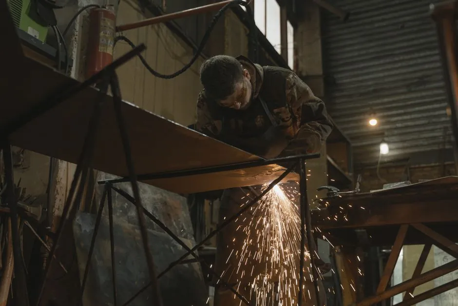
Projection welding remains the most common method for nut and M- or T-thread bolt attachment in automotive body-in-white, where a modern car body contains roughly 300 welded and punched fasteners carrying axle, seatbelt, steering-column, and grounding loads [S3]. Stud welding, by contrast, is a one-sided arc process that finishes a single fastener in under one second and works on parent material down to 0.7 mm in the capacitor discharge variant [S1][S4].
The two processes converge on the same outcome, a permanent metallic bond between fastener and sheet, but diverge sharply on heat source, fixturing, and base-metal preparation. Engineers selecting between them weigh one-side access, sheet thickness, fastener grade, and required throughput per shift; the wrong choice shows up as expulsion, incomplete fusion, or a fatigue crack at the weld toe [S1][S3].
Process Mechanics: Arc Fusion vs Embossed Projection Collapse
Resistance projection welding localises current through raised features on the fastener, typically 3-4 small projections, so the heat concentrates at the projection tips and the surrounding sheet metal acts as the secondary conductor [S1]. The weld cycle has three discrete phases: projection contact with the mating sheet, current-driven heating to welding temperature, then rapid collapse of the softened projection under electrode force to form fusion [S3]. Because the projection itself becomes the resistive element, projection welding draws less current than a comparable resistance spot weld of the same nominal diameter [S3].
Stud welding uses an electric arc between the fastener tip and the workpiece, then plunges the fastener into the molten pool under spring return pressure. Capacitor discharge (CD) stud welding stores energy in capacitors and releases it as a high-current pulse, vaporising a small ignition pip and fusing the stud flange in roughly a millisecond-scale event; drawn-arc stud welding lifts the stud against a ceramic ferrule to draw a sustained arc, then plunges the stud into a contained molten pool [S1][S4]. The CD variant runs off 110 V or 240 V North American mains, or 220 V in Europe, with no high-pressure clamping [S1][S4].
Base-Material Range and Minimum Thickness
CD stud welding is specified for parent material at or above 0.7 mm thickness, which puts it in the thin-sheet and appliance-enclosure domain [S4]. Drawn-arc stud welding has a rule-of-thumb lower limit of one-third of the stud diameter in parent-material thickness, reflecting the larger molten pool and higher thermal load of a sustained arc [S4]. Short-cycle stud welding, a hybrid that uses CD-style studs but the arc approach, drops to 1.5 mm minimum parent thickness and tolerates dirtier or less-flat surfaces than straight CD [S4].
Resistance projection welding handles low-carbon steel cleanly because the higher electrical resistivity of the steel concentrates heating at the projection; high-carbon steels and aluminium alloys are notably harder to weld, with aluminium requiring higher current and producing brittle joints in many resistive setups [S2][S4]. Weld nuts and bolts commonly ship with either an annular projection or three to four separate projections, and the annular geometry is preferred for fatigue-loaded joints because it offers fewer crack initiation points than discrete bumps [S3].
Side Access, Fixturing, and Production Geometry
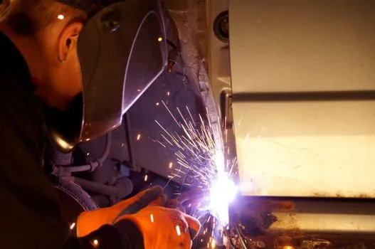
Stud welding needs access to only one side of the assembly, which is the decisive advantage on closed-section chassis, HVAC cabinets, and tubular furniture where the back side is unreachable or would require a hole [S1][S4]. Drawn-arc studs require a ceramic ferrule per weld that contains and shapes the molten metal and is then knocked off, so the process leaves a small ferrule waste stream that must be collected and disposed of as a consumable [S4]. A closer look at ferrule behaviour in production is covered in ceramic ferrule practice.
Projection welding needs both sides accessible: the electrode on the sheet side, the welding electrode on the fastener side, and a follow-up head that tracks the projection as it collapses. Slow follow-up causes metal expulsion before the parts have been brought together; excessive force collapses the projections prematurely and leaves incomplete fusion in the centre [S3]. For CD stud welding the entire rig is handheld, weighs a few kilograms, and is fed by a small benchtop power unit, so the capital footprint per workstation is a fraction of a projection-welding press with its transformer stack and water-cooled holders. For larger CD work, CD stud welder capacitor bank sizing becomes the controlling design parameter, and stud welder power unit alternatives is a useful cross-reference when moving off a fixed-output box.
Decision Matrix: Choose by the Real Constraint
Across the four criteria that drive 90 percent of fastener-process selections, the two methods line up as follows. One-side access: stud welding wins, no electrode needed on the reverse face. Minimum parent thickness: CD stud welding at 0.7 mm beats projection welding's typical 0.8-1.0 mm working floor on mild steel [S4][S3]. Cycles per minute on a high-volume nut line: projection welding wins, because multiple projections on a single part can collapse in one press stroke, while stud welding is one stud per gun trigger. Electrode and consumable cost per 1000 joints: stud welding uses a cheap ferrule (drawn arc) or no ferrule (CD), while projection welding uses shaped copper-alloy electrodes, commonly CuCrZr or Class 2 copper, that must be dressed and replaced on a wear cycle [S2][S4].
The direct corollary is a per-use-case split. Choose stud welding when the back of the assembly is hidden, when the parent material is under 1.0 mm, when fastener variety is high (mixed M6, M8, M10 on the same line), or when the line is job-shop rather than high-volume. Choose resistance projection welding when the part is a stamped body panel with dozens of nuts per piece, when a single press can land 4-8 projections in one stroke, and when the line is dedicated to one fastener geometry for hundreds of thousands of cycles [S1][S2][S3].
Failure Modes and Parameter Levers
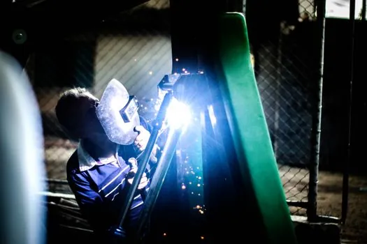
Projection welding fails in two characteristic ways. Undercurrent leaves the projection collapsed but unfused at the centre; overcurrent boils the projection and expels molten metal before the electrode force has bottomed out, leaving a pitted weld and possible burn-through on the sheet [S3]. High-strength steels amplify both failure modes, which is why impulse welding is sometimes specified to control the heating rate on advanced high-strength steel weld nuts [S3]. Electrode force has a narrow band: too low and the projection never flattens, too high and the projection collapses before fusion temperature is reached and the centre never bonds [S3].
Stud welding fails in roughly the mirror-image pattern. Too little lift or too short an arc time leaves the stud sitting on a cold parent surface with incomplete fusion at the interface; too much lift or too long an arc time blows the molten pool out of the joint and leaves a porous, under-filled weld [S4]. Drawn-arc welds without the ceramic ferrule run slags and porosity because the arc is no longer contained, which is the practical reason ferrules are not optional on most production drawn-arc setups [S4]. Across both processes, the inspector's first pass on a suspect weld is a simple torque test and a visual on the weld toe, looking for expulsion craters, undercut, or visible lack of fusion at the projection or flange edge [S3].
Standards, Equipment, and Sourcing Notes
Resistance projection welding equipment is governed by the same family of resistance-welding standards that cover spot and seam welding, with electrode material specifications calling out CuCrZr and Class 2 copper for high-conductivity holders on nut and stud lines [S2]. Stud welding equipment is sold in two distinct tiers, lightweight CD benches (110-240 V mains input, kVA-class output) and heavier drawn-arc inverter power sources with a transformer and water cooling, and the two tiers are not interchangeable: a CD power source cannot deliver the sustained arc that drawn-arc studs require [S1][S4].
For background on the equipment side, the stud welder encyclopedia entry covers the operating principles and the welding cutting tool page covers the broader thermal-joining tool family. Where fastener attachment has to be evaluated against adjacent joining processes, arc welder covers the related fusion processes and is a useful baseline for throughput comparison.
The next trackable signal is the move of automotive programs from low-carbon steel body panels to advanced high-strength steel and press-hardened boron steel: both projection and stud welding need revised weld schedules for these grades, and suppliers are publishing per-grade current/force/time windows through 2026 as more programs ramp. A second watch item is the gradual shift of small-batch fabricators from drawn-arc to short-cycle stud welding, which removes the ferrule consumable and shortens cycle time on 1.5-3.0 mm mild steel at the cost of requiring shielding gas on the gun.