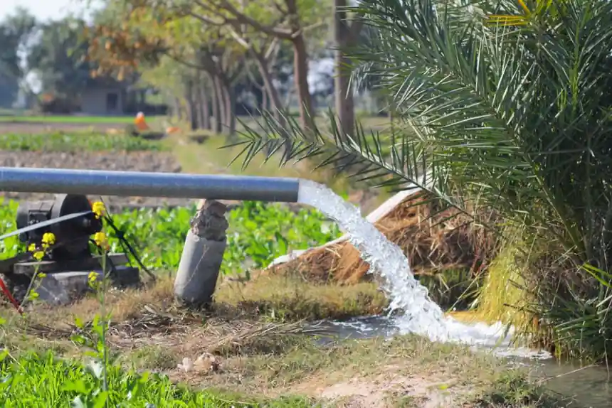
A 3/4 HP residential submersible well pump with roughly 9 impeller stages will deliver about 10 GPM at 150 ft of total dynamic head, while a 1.5 HP / 14-stage unit pushes closer to 10 GPM at 300 ft of head, because each stage adds incremental pressure inside the slim 4-inch housing [S2].
The pump, motor, splice, and drop pipe work as a single column, and four failure modes dominate field service: dry-run, sand ingestion, single-phase drop-out, and a leaking splice. The install sequence below addresses each one with a concrete spec or acceptance check.
Sizing Gate: Static Level, Drawdown, and Total Dynamic Head
Match the pump to the well, not to the house fixture count: take the static water level and the projected drawdown, add the pressure-tank setting in feet of head (50 psi ≈ 115 ft), then add friction loss in the drop pipe at design GPM, and the sum is total dynamic head (TDH) the pump must produce [S2][S1].
Most residential submersible units fit a 4-inch well casing because the multi-stage centrifugal stack is built into a 4–6 inch OD housing, and going below 4 inches is the practical floor for a hermetically sealed oil- or water-filled motor [S2]. For a 200 ft deep well supplying a typical 3-bedroom home, the TDH math usually lands between 230 and 280 ft, which puts a 1 HP 12-stage pump in the center of the envelope rather than the cheapest 3/4 HP model [S2].
Submersible vs Jet Pump: When Submersible Wins, When It Loses
Submersible pumps push water from below the waterline, so they are not bound by the ~25 ft suction lift ceiling that caps shallow-well jet pumps, which is why jet-pump installations must be within roughly 25 vertical feet of the static water level [S1][S2].
Pick a submersible when the static water level sits below 25 ft, when the well is deeper than ~25 ft, or when noise at the house is a concern, because the surrounding water cools the motor windings and silences operation, which is why field service lives of 10–15 years are common on residential submersible units versus 5–8 years on comparable surface jet pumps in similar duty [S2]. Pick a jet pump when the well is shallow and the homeowner wants an above-ground unit that can be serviced without pulling the column, since jet pumps are easier to service and parts are widely available [S1].
Drop Assembly: Torque Arrestor, Safety Rope, and Splice
Install the pump on a torque arrestor above the foot of the drop pipe and a separate safety rope (commonly 3/16 in or 1/4 in stranded polypropylene or nylon) clamped to the pump body, so the pump cannot free-fall down the casing if the drop pipe thread or coupling ever fails [S2].
The electrical splice between the drop cable and the wet-end motor lead is the single most failure-prone joint in the column: use a submersible-rated splice kit (heat-shrink with mastic or epoxy resin block, never a generic wire nut), and respect the kit's specified shrink temperature and potting cure time before the assembly touches water [S2]. For comparable drop-pipe work in commercial water systems, the same spec discipline shows up in magnetic drive pump selection, where the cable entry and seal gate decides the difference between a 5-year and a 15-year mean time between failures. Bury the splice below the drawdown by at least the pump's own length so it never sees air during a pump-down cycle.
Wiring: 230 V Single-Phase, Two-Wire vs Three-Wire, Breaker Sizing
A two-wire 230 V submersible pump needs only two power conductors and a ground, runs directly off a single-phase 230 V supply, and requires no control box at the surface, which is the main reason retrofit and DIY well owners pick the two-wire configuration [S3].
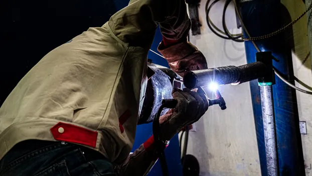
A three-wire 230 V unit adds a start winding and a control box (or start capacitor + relay) at the surface, which lets the motor develop higher starting torque and is the preferred pick for deeper wells where starting current and starting torque both matter [S3]. For the wider arc-welding and pipe-install wiring picture, see the arc welding machine picks for plumbing pipe work reference.
Check Valve, Pressure Tank, and Dry-Run Protection
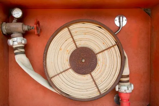
Install a spring-loaded check valve at the pump discharge or just above it in the drop pipe, plus a second check valve at the surface ahead of the pressure tank, so the column cannot back-spin and the tank cannot leak the pump dry between cycles [S2].
Set the pressure tank pre-charge to 2 psi below the pump cut-in pressure (for a 30/50 switch, pre-charge ≈ 28 psi), and wire a low-water cut-off or pump protection relay that trips on undercurrent when the well draws down past the pump inlet, because running a submersible pump dry destroys the mechanical seal and the thrust bearing in minutes, not hours [S2]. The pre-charge check is one of the two acceptance tests that separates a clean install from a chronic short-cycling failure.
Acceptance Test and When to Walk Away
Run the pump to a steady discharge, then close the furthest valve and time the pressure rise from cut-in to cut-out: the pressure tank must reach cut-out within a reasonable window and the pump must shut off on the pressure switch, not on the breaker. Measure the no-flow current with a clamp meter and compare it to the motor nameplate FLA plus 10% as the ceiling; anything above that on a new install means a binding impeller, a mis-phased supply, or a mis-sized drop pipe and the unit should be pulled before sand destroys the stages [S2][S3].
Replace, do not repair, when the wet-end draws more than 5% over nameplate amps after a new install, when the splice has been submerged without a submersible-rated kit, or when the pump is older than 8–10 years and the bearings are audible at the wellhead; repair is sensible only for a tripped breaker on a healthy unit, a failed pressure switch, or a failed pre-charge valve on the tank [S2]. A few trackable signals to watch through the rest of 2026: the 4-inch stainless stage count continues to push higher (current residential builds reach 18 stages on 1.5 HP frames for 400 ft+ heads) [S2], and two-wire 230 V drop-in replacements keep displacing three-wire retrofits on 1 HP and below because the eliminated control box removes the most common service call [S3].
Spec-level background on the components involved: linear guide, and crossed roller guide.