
A self-priming centrifugal pump does not need a foot valve or external priming line, but it absolutely needs the suction piping, foundation, and shaft alignment to be within tight tolerances: ≤0.05mm parallel misalignment, ≤0.05mm/m angular, suction lift capped at 5m, and a primed pump body filled to roughly 2/3 of chamber volume before the first start [S3][S5].
The mechanical reason is built into the casing: a reservoir, recirculation port, and air-separation chamber work together to evacuate air from the suction line; any leak, high lift, or misaligned coupling collapses that vacuum and the pump will churn, heat, and destroy its mechanical seal within minutes [S7][S2]. This article walks through the install steps, the comparison between self-priming and standard end-suction pumps, the failure modes that show up in the first 3-4 hours of operation, and the maintenance checkpoints that decide service life.
Foundation and Base Plate: Concrete, Anchor Bolts, and Grout Cure
Large self-priming units sit on a concrete foundation cast to the pump's basic footprint, with anchor bolts pre-embedded during the pour; small self-priming units (typically under ~50kg) can be set directly on a leveled surface without a poured foundation [S1]. Foundation depth should be sized to carry pump weight plus dynamic loads, with BZ-series best-practice guidance calling for foundation capacity at minimum 3x the static weight of the unit [S10].
Concrete pad thickness of at least 150mm is the practical floor, with anchor bolts set to base-plate dimensions and the plate leveled to a tolerance of 0.1mm/m before non-shrink grout is poured [S3]. After grouting, 48 hours of curing time is required before the pump is set; placing the pump on wet grout will float it out of level as the grout cures and will re-introduce the very misalignment the pour was meant to prevent [S3]. For a wider view of how installation discipline maps onto adjacent rotating-equipment spec work, the industrial lubricant selection spec map for oil and gas covers the bearing-lubrication side that follows once alignment is correct.
Shaft Alignment: Coupling, Coaxiality, and the 0.1mm Rule
When the self-priming pump and motor are direct-coupled, coaxiality between the pump shaft and the motor output shaft is the single largest determinant of smooth operation and bearing life, and the allowable deviation of different-shaft degree (parallel offset) is 0.1mm [S2]. Tighter BZ-series tolerances take this down to ≤0.05mm parallel and ≤0.05mm/m angular, measured with a dial indicator for parallel and feeler gauge for angular [S3].
Height difference between pump and motor shafts is corrected by shimming copper or iron under the motor feet before the foundation bolts are finally torqued [S2]. After 3-4 hours of trial operation, a final inspection of the shaft and coupling is mandatory: any sign of fretting, hot bearing housings, or coupling bolt loosening means the alignment walked under load and must be re-checked before the unit is handed over [S2]. Foundation bolts themselves are torqued to the manual value, not "snug"; loose anchor bolts let the base plate rock and re-create misalignment every time the motor starts [S3].
Suction Piping: 5m Lift Cap, Filter Sizing, and the No-Leak Rule
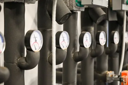
Self-priming height is the limiting hydraulic parameter, and the install spec is hard: suction-port installation height must not exceed 5m, with the practical target being as close to or below the lowest water level of the source as possible, and the suction line kept as short as possible with the minimum number of elbows to shorten self-priming time [S2][S5]. A simple field rule is "3m lift on clean water" = actual lift scaled by medium density, so a denser liquid effectively lowers allowable lift for the same pump [S5].
The suction line must be airtight: any valve or flange leak defeats the priming cycle because the gas the pump is trying to evacuate keeps getting replenished through the leak path [S2]. A filter on the inlet is required, with effective flow area 2-3x the suction pipe cross-section (Nanfang guidance is 3-4x), and the filter must be cleaned on a schedule, not after the pump starves [S2][S5]. For solids-laden or fibrous service such as sewage, a strainer sized too small becomes the prime-mover killer within days. Suction and discharge lines must have their own supports: the pump casing is not designed to carry pipeline weight, and a hanging discharge run will warp the casing, break the foot, and crack the volute [S2][S4].
Comparison: Self-Priming vs Standard End-Suction Centrifugal on Install Criteria
On four install criteria, the difference between a self-priming pump and a standard end-suction centrifugal pump is sharp: priming requirement, foot valve, suction lift tolerance, and dry-run tolerance. A standard end-suction unit typically needs a foot valve, an external priming line or vacuum assist, and a flooded suction to start; a self-priming unit can exhaust air through its own recirculation chamber and start with a flooded or partially flooded pump body [S7][S9].
On suction lift, both are limited, but the self-priming unit's recirculation design lets it pull air out of the suction column to a practical 4-5m lift without losing prime, whereas a standard end-suction unit will air-bind and stop pumping at much less lift unless the suction is positively flooded [S4][S5]. On dry-run tolerance, neither is rated for it: the self-priming pump's mechanical seal still needs the priming liquid to be present at first start, and continuous dry running on either type will destroy the seal in minutes, so the install spec explicitly requires the pump body to be filled to roughly 2/3 of chamber volume before power-on [S3][S4]. On piping complexity, the self-priming unit eliminates the foot valve and external priming line, which simplifies the install and reduces one leak path, but the trade-off is that the suction line still must be airtight, so total piping complexity drops by one component, not by a factor [S9].
Electrical, Grounding, and Pre-Start Commissioning
Motor wiring must match the nameplate: 380V/50Hz is the common three-phase standard on Chinese-supplied units, with cable cross-section sized to motor power and overload plus short-circuit protection fitted on the line [S3]. Protective grounding resistance must be ≤4Ω, and the pump and pipeline together must meet the electrostatic-grounding resistance specified for the medium being handled, especially for flammable or explosive fluids [S2][S3]. Rotation direction is verified with a no-load bump or first-start observation: clockwise viewed from the motor end is standard, and reversed rotation on a centrifugal pump delivers a fraction of rated flow and head, which can look like a "priming failure" when the real cause is the phase sequence [S3][S4].
The pre-start checklist is short and non-negotiable: foundation bolts torqued, alignment within tolerance, bearing lubrication applied, priming water at 2/3 chamber, rotation direction confirmed clockwise, suction valve fully open, discharge valve 1/4 open [S3]. On first start, the discharge valve is opened gradually to the desired flow while current, vibration, and noise are monitored, with bearing temperature held under 80°C, vibration under 4.5mm/s, and noise under 75dB as the running-parameter ceiling [S3]. If any of these limits is breached, the unit is stopped immediately and the underlying cause (alignment, lubrication, cavitation) is addressed before the next attempt. For related rotating-equipment electrical work, the time relay sizing guide covers the motor-starter sequencing side that pairs with this commissioning step.
Failure Modes: Cavitation, Water Hammer, and Crystallising Media
Cavitation shows up as noise above 75dB, vibration above 4.5mm/s, and a head/flow curve that collapses at high lift; the root cause is almost always NPSH violation, where the installation height of the pump exceeds the pump's NPSH allowance once pipe-line losses and medium temperature are accounted for [S3][S5]. Hot media also push the mechanical seal past its rating and require a cooled seal arrangement; the install spec requires cooling measures on the mechanical seal when medium temperature is high enough to risk static-ring deformation or cracking [S5].
Water hammer on sudden stoppage is mitigated with a check valve on the discharge line of high-lift self-priming units; without it, the returning column of liquid can fracture the volute or blow a seal [S5]. For magnetic-drive self-priming pumps such as the ZCQ, the media restriction is hard: crystallising particles are forbidden because crystals score the magnet coupling and the static seal pair, and continuous operation with a closed discharge is also forbidden because the magnet coupling cannot shed heat without minimum flow [S4][S5]. For routine maintenance on the suction side, pairing a self-cleaning filter ahead of the pump cuts the cleaning interval and protects the impeller from stringy debris in sewage service.
When to Stop and Escalate Instead of Re-Prime
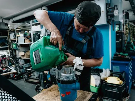
Repeated priming failures after a correct first install point to a leak in the suction line, a clogged strainer, or a drop in source-water level below the calculated NPSH, and these are not fixed by re-priming; the suction line must be re-pressure-tested and the strainer pulled [S2][S5]. Bearing temperature rising past 80°C under load is a lubrication or alignment problem, not a "run it in" problem, and continuing to run will destroy the bearing and the shaft [S3]. For media above the pump's rated viscosity, the pump curve and motor power shift; the OEM must be consulted before commissioning because the motor may not have the thermal margin for the new duty point [S5].
Track for the next maintenance interval: re-torque anchor bolts at 6 months and 12 months (grout can creep under cyclic load), pull and inspect the suction strainer at the same cadence, and log bearing temperature and vibration at each visit so drift is visible before failure. For a broader look at how installation discipline maps across industrial process equipment, the open channel flowmeter sizing spec map covers the site-fit side that often dictates where a self-priming pump can be physically sited in a treatment works.