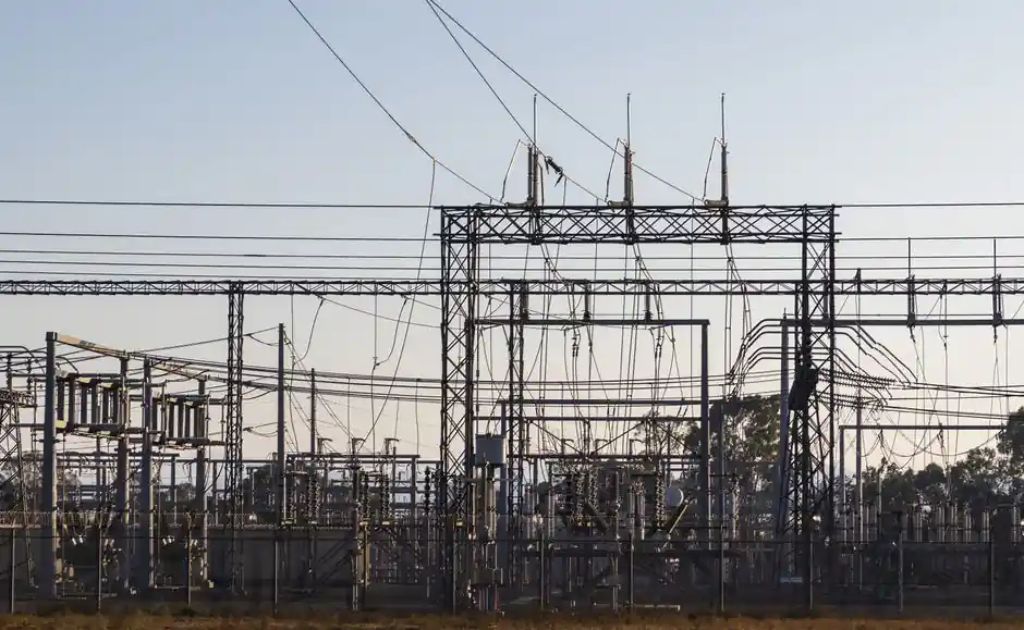
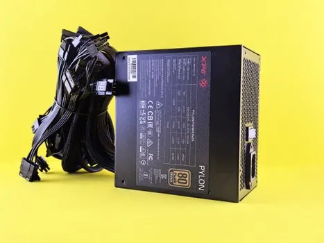
A switching power supply (SMPS) is the default workhorse of modern electronics because it converts AC or DC input to a regulated DC output at 85–95% efficiency by chopping the input at 20 kHz to several MHz, then filtering the pulsed energy through small magnetic components [S4]. Compared to a linear supply that dissipates excess voltage as heat, an SMPS wastes far less energy, runs cooler, and weighs a fraction of the equivalent linear brick for the same output power [S1][S4].
Selection in 2026 is driven by four numeric gates: input voltage range, output voltage and continuous current, peak/transient current, and the minimum efficiency the thermal budget can tolerate. Cross those before you compare brands, topologies, or price, and you cut roughly 80% of the noise out of the RFQ. The articles on DC power supply selection criteria and industrial UPS sizing sit next to this topic because both follow the same load-first methodology.
Linear vs Switching vs Hybrid: A Three-Way Comparison
Linear supplies typically run 30–50% efficient, large and heavy because of the 50/60 Hz mains transformer, and very quiet on the output; switching supplies run 80–95% efficient, weigh a fraction of the equivalent linear unit, and emit higher EMI that must be filtered [S1][S2][S4]. A linear regulator burns the difference between input and output voltage as heat, so its losses scale with the Vin-Vout drop, which is why a 24 V to 3.3 V linear dropper is impractical above a few hundred milliamps.
Use a linear supply when output ripple and conducted noise must stay below roughly 1 mV RMS, when the load is under 50–100 W, or when the application (audio front-ends, lab references, medical signal chains) cannot tolerate SMPS switching artefacts even with filtering [S2]. Use a switching supply for everything else above 100 W, and especially for any universal-input AC/DC converter, battery-powered DC/DC, or compact embedded design. Hybrid approaches (linear post-regulator after an SMPS pre-regulator) cover the small niche where you need both high efficiency and very low ripple, but at the cost of two stages and extra board area.
Load Profiling: The Numbers That Drive Every Other Decision
Engineers should write down four current values before opening a datasheet: nominal continuous, peak repetitive, peak surge, and standby/light-load. Keysight's selection guide lists typical rails as 3.3 V or 5 V at 50–500 mA for microcontrollers and sensors, 12 V or 24 V at 0.5 A to several amps for LED drivers, 15 V to 28 V at 1 A to 10 A for RF amplifiers, and 24 V to 48 V at multi-amp to hundreds of amps for motor controllers [S2]. Those numbers, not the nameplate wattage, decide which supply you actually need.
Continuous rating should cover at least 100% of nominal load and ideally 125–150% for design margin; peak handling must absorb inrush events like motor starts, capacitor banks, or RF PA bursts without current-limit foldback [S2]. Underpowering causes droop, instability, and brown-outs on neighbouring rails; over-spec'ing by more than 3x burns money on a unit that will never reach its rated efficiency at your actual operating point. The related power supply topology overview walks through how those load profiles map to buck, boost, and buck-boost stages.
Topology Choice: Buck, Boost, Flyback, Forward, LLC
Topology choice follows input/output voltage ratio and power level. For non-isolated DC/DC at tens of watts, buck (step-down) and boost (step-up) dominate; buck is the most common because most digital rails step down from 12 V, 24 V, or 48 V buses [S3][S4]. For isolated AC/DC converters in the 50–500 W range, flyback is the cheapest and most common single-switch topology, and forward converters handle the 100–500 W range where flyback transformer stress becomes uneconomic.
Above roughly 500 W and into the kilowatt range, LLC resonant and phase-shifted full-bridge topologies win on efficiency (often 94–97% at full load) and on EMI because the switching nodes swing in a softer, sinusoidal manner [S3]. A well-designed SMPS typically runs at 85–95% efficiency across its operating range, but that figure is only meaningful at your real load, not the marketing peak. Buck converter inductor ripple current is usually targeted at 30–40% of applied load current to keep the feedback loop reading a clean signal without entering discontinuous conduction mode [S4].
Input, Isolation, and PFC: What the Datasheet Quietly Assumes
Universal AC input (85–264 VAC, 47–63 Hz) is now standard on most AC/DC SMPS modules, but the hold-up time, inrush current limiter, and surge immunity (typically 1 kV or 2 kV per IEC 61000-4-5) are where cheap units get separated from industrial-grade ones. Active Power Factor Correction (PFC) is mandatory above 75 W in most jurisdictions under IEC 61000-3-2 harmonics limits, and a PFC stage typically pushes overall efficiency down 1–2 percentage points but brings line current THD below 10% at full load [S1].
Isolation voltage is a hard number for medical, ITE, and industrial installations: 3,000 VAC or 4,000 VAC input-to-output is common, with reinforced insulation per IEC 62368-1 or IEC 60601-1 depending on the end application. If your load connects to a battery or to non-isolated user-accessible circuitry, treat the isolation voltage as a safety-critical line item rather than a checkbox. The power distribution architecture context covers how isolation choices ripple through the rest of the cabinet design.
Thermal, Derating, and Reliability
An SMPS rated at 100 W at 25 °C may only deliver 60 W at 50 °C ambient; every quality datasheet publishes a derating curve, and the safe approach is to load the supply to no more than 70–80% of its 25 °C rating to leave margin for fan failure, dust, and altitude [S1][S2]. MTBF figures in the 200,000–500,000 hour range are typical for industrial AC/DC modules, but those numbers assume operation within the derated envelope, not at the nameplate maximum.
Forced-air cooling extends output but introduces a moving part, which is why convection-cooled supplies are preferred in sealed enclosures or dusty sites. Conduction-cooled or baseplate-cooled modules bolt to the chassis and push 100–300 W without fans, at the cost of strict heatsinking discipline. Efficiency matters most here: the 85–95% SMPS range against a 40–60% linear baseline means 5–10x less waste heat for the same delivered power, which directly shrinks heatsink size and lets you pack more channels into the same panel [S4].
Compliance, Standards, and the RFQ Checklist
For an AC/DC industrial supply, the minimum compliance stack is usually UL 62368-1 or IEC 62368-1 (ITE/audio/video safety), IEC 61000-4-x series for EMC immunity, IEC 61000-3-2 for harmonic current, and a regional mark (CE/UKCA/UL/cUL/CCC). Medical applications add IEC 60601-1 with its 2x MOPP isolation requirements; railway adds EN 50155 with input ranges that must survive brownouts and surges on the overhead line. None of these are optional in a serious RFQ, and a unit with no third-party certification should be excluded from industrial bids regardless of price. [S1]
A pragmatic 2026 selection checklist: confirm the four load numbers (continuous, peak, surge, standby), pick topology by power and isolation, verify efficiency at your real load not the marketing peak, demand the derating curve, list the safety/EMC/standards marks, and reject any vendor that will not publish a measured MTBF or an inrush/hold-up waveform. The cross-discipline selection pattern in industrial UPS procurement and the DC power supply selection criteria pages both reinforce the same load-first, standard-second, brand-last sequence.
Two trackable signals for the rest of 2026: the rollout of higher-density silicon carbide (SiC) and gallium nitride (GaN) primary switches, which keeps pushing SMPS efficiency past 96% in the 1–5 kW bracket, and the slow tightening of EU EcoDesign standby rules below 0.1 W no-load consumption, which is squeezing out the cheapest 5 V wall-warts.
Background reading: Nuclear Power Procurement Strategy 2026: Specs, Sourcing, and Award Criteria.