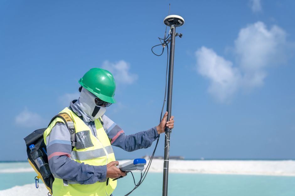
Total station installation is a three-phase field procedure: tripod and tribrach setup, instrument leveling and indexing, then prism or prismless target acquisition, with on-site acceptance gated by 2″–5″ angular accuracy and 300–500 m prismless range limits [S1][S2].
The instrument consolidates horizontal angle, vertical angle, slope distance, horizontal distance, and height-difference measurement in a single optical-mechanical-electronic head, replacing the optical theodolite's graduated circle and micrometer with a photoelectric scanning encoder that removes manual readout error [S2]. Once the unit is set on a station, the full measurement set for that station completes without re-sighting, which is the operational origin of the "total station" name [S2].
Phase 1: Tripod, Tribrach, and Coarse Centring
A heavy-duty aluminium or wood tripod rated for at least 4.5 kg instrument mass is set with legs spread to roughly 60° from vertical, head roughly horizontal, and the foot shoes pressed firmly to prevent settlement during the 10–30 minute observation window [S2].
The tribrach is locked onto the tripod head, then the optical plummet (or laser plummet on modern units) is used to align the instrument's vertical axis over the ground mark; lateral offset greater than ±1 mm at plumb height typically requires a tripod reposition rather than a tribrach shift, because correction past that range over-tilts the head and biases subsequent angle readings [S2]. The three footscrews are then brought to mid-travel so each has equal remaining adjustment range — a hard rule among survey crews because end-of-travel screws introduce backlash during fine leveling.
Phase 2: Fine Leveling, Indexing, and Calibration
Fine leveling uses the electronic bubble or tubular level aligned parallel to two footscrews; rotate 90° to the third screw, recentre, and iterate until bubble drift is under one division on a 30″/2 mm tubular vial, which corresponds to a vertical-axis tilt of roughly 10″ — the practical acceptance threshold for 2″ angular accuracy instruments [S2].
Indexing (also called zero-set or vertical-index calibration) is run on every setup: sight a clean target, press the index key, rotate the telescope 360° about the horizontal axis, and confirm residual vertical angle reads 0°00'00" ±2″; a reading drifting past 5″ between warm-cold cycles points to compensator drift or a bent horizontal axis and the unit is pulled from service [S2]. Atmospheric correction (ppm input for temperature and pressure) must be set before distance work — a 10 °C error at 500 m prismless range introduces roughly 1–2 ppm scale error, which exceeds most 2 mm + 2 ppm distance specs and is the most common field-acceptance failure mode crews encounter. Reference setups for related optical instruments, including laser levels, follow a similar compensator-index discipline discussed in the laser-level installation guide on site setup and acceptance.
Phase 3: Target Acquisition, Prism vs Prismless Selection

Prism-mode measurement with a single 360° prism is specified wherever sub-millimetre distance accuracy is required; standard prisms deliver range to 3,000–5,000 m depending on atmospheric conditions and instrument class [S1][S2].
Prismless (reflectorless) mode, offered on models such as the Mato MTS-1202R (500 m) and MTS-602R (300 m), uses a coaxial visible laser and is the correct choice for building-face, tunnel-profile, and stockpile-volume work where prisms cannot be placed safely; range falls to 300–500 m and accuracy loosens to roughly 3 mm + 2 ppm versus 1 mm + 1.5 ppm on prism mode [S1]. Backlight, reflective paint, and high-gloss stone surfaces can return false echoes; the standard mitigation is to matte the target zone with surveyor's chalk or shoot at a 30°–60° off-normal incidence angle to suppress specular reflection. For construction-machine guidance work that pairs the total station with on-board sensors, similar environmental-fit logic governs crane scale IP and connectivity selection, where site dust and humidity push the IP and cable spec the same way.
Criteria Map: Instrument Class vs Accuracy, Range, Environment
Selection breaks on three decision criteria — angular accuracy, prismless range, and environment rating — and maps cleanly to three typical classes: 2″ high-precision (e.g. Leica TS03 2″ model, used for control traverse and deformation monitoring where sub-2 mm positional drift is the acceptance bar), 5″ mid-range (e.g. Mato MTS-602R, general construction layout with ±5 mm stakeout tolerance), and 5″/300 m long-prismless (e.g. Mato MTS-1202R 500 m, mining and tunnel face profiling) [S1].
Operating-temperature limits of −20 °C to +50 °C are common across the listed units, with IP54 or IP55 dust/water ingress required for any site where rain, concrete slurry, or drill dust is present; below IP54, foam sleeve covers are mandatory in tunnel work. For replacement-part selection — display screens, keypads, encoder strips — the parts of total station category from Hengyide Group catalogues TCR/TS-series displays, batteries, and mainboards, with each spare part carrying a model-code match requirement before replacement [S1]. The deeper instrument-class discussion in the total station encyclopedia entry gives the full set of angle-encoder and EDM module options that drive that class split.
Use Cases, Failure Modes, and When NOT to Repair

Field failure modes cluster into four buckets: (1) compensator error after impact drop, (2) horizontal-axis collimation drift from thermal shock, (3) EDM module failure shown as erratic distances or constant offset on a known baseline, and (4) keypad/display failure from dust ingress past a degraded gasket [S1][S2].
Symptom-to-action: bubble drift that won't stabilise after re-leveling = bent tripod or warped tribrach, replace the tripod before resuming; vertical-index residual drift past 5″ on warm-up = return to service centre for compensator calibration, do not field-adjust; distance offset constant on a calibrated baseline = EDM optical-path contamination or laser diode end-of-life, both factory-repair; display segment loss = spare-part replacement using a model-matched screen (e.g. TCR805 display) ordered against the instrument serial [S1]. Do not field-replace encoder strips or laser diodes — cleanroom assembly and optical-bench alignment are required, and the cost of a failed field attempt typically exceeds the OEM flat-rate repair. The maintenance-cost pattern for optical-electronic gear mirrors the 10-year laser-level TCO model — annual calibration, battery replacement at year 3–5, and display/encoder refurbishment at year 7–9 dominate lifecycle spend. Acceptance criteria for any returned-to-service unit: 2 mm + 2 ppm distance repeatability on a 30 m calibrated baseline over five iterations, angular closure under 3″ on a four-quadrant observation, and compensator-index residual under 2″ at 0°, 90°, 180°, 270° rotation [S2].
Trackable next signals: Hengyide Group's Shanghai-Pudong facility output volume for prismless 300/500 m Mato MTS-602R and MTS-1202R units, and any OEM release of sub-1″ robotic total stations with prismless range past 1,000 m — both will reset the class-2/3 selection map above. Field crews running these instruments on dynamic-compactor or pile-driving projects should also review the dynamic-compactor installation spec map, since total-station stakeout tolerances for those rigs fall in the 5 mm–10 mm band and match the mid-range instrument class directly.
Spec-level background on the components involved: linear guide, and crossed roller guide.