A dynamic compactor — also called a dynamic compaction rig or heavy-tamper unit — is best installed as five sequential phases (foundation, guide-mast alignment, hoist-trip assembly, hydraulic/PLC integration, drop-test commissioning) rather than a single crane day, because the 10-40 tonne ram and 15-25 m mast impose strict verticality, energy-transfer, and ground-clearance tolerances that, if missed, propagate into skewed impact craters and lost compaction depth.
This guide covers free-drop high-energy tampers (impact energy roughly 3,000-25,000 kN·m per drop) used on reclamation fills, mine tailings, and loose-cohesionless soils, and is written for the project engineer coordinating the civil, mechanical, and electrical trades on site. It is NOT a maintenance procedure for an in-service rig.
Phase 1 — Foundation, Pit, and Crane-Pad Prep Before the Rig Arrives
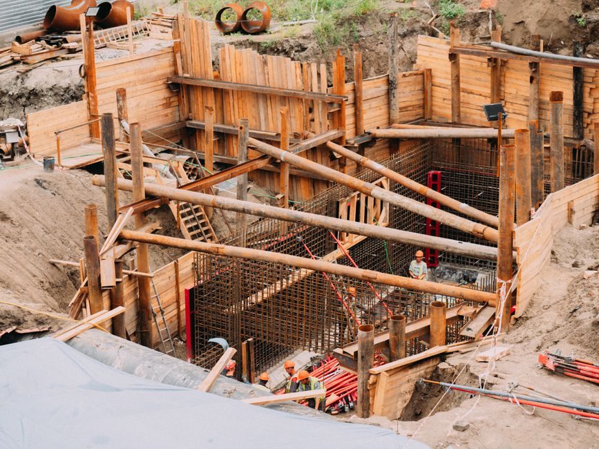
The dynamic compactor base footprint and any recoil-absorption pit must be excavated and cured at least 7 days before the unit is erected, with a 25-30 MPa reinforced-concrete pad dimensioned to the OEM drawing (typical pad: 6 m × 6 m × 1.2 m thick for 15-20 t rams) so that mast-base bolt loads do not deflect under repeated impact [S4]. The recoil pit, where specified, is sized to the ram's drop-stroke plus a 0.5 m clearance margin and is drained to a sump — free water inside the pit is a documented cause of hydraulic-cylinder contamination on first start [S4].
Site access for a 80-120 tonne crawler crane must be graded to within 1% slope and proof-rolled, because lifting the mast (typical mass 8-12 t for a 20 m unit) at an out-of-level crane induces side-loads that crack the guide-rail weldments during upending. A soil-bearing check of ≥150 kPa at the crane-stance pad is the minimum I accept before authorizing the lift; below that, lay crane-mat timber or steel plates.
Skip Phase 1 prep on the assumption the OEM will "make it fit" — they will not, and rework on a cured pad is roughly 3-5× the cost of doing the pour correctly the first time. Related heavy-equipment installation logic on trenchless or buried assets is laid out in the fire-hydrant bury-depth spec map, which uses the same pit-and-pad sequencing principle.
Phase 2 — Mast, Guide Rails, and Trip-Hoist Alignment
Guide-rail verticality is the single most-measured tolerance on a dynamic compactor install: target ≤5 mm deviation over the full 15-25 m mast height, verified with a theodolite on two orthogonal faces before the first hoisting cable is tensioned, because a tilted mast converts vertical drop energy into horizontal sway and reduces effective depth of influence by an estimated 20-40% per degree of lean. [S3]
The hoist drum, sheave block, and automatic trip mechanism (cable-release, hydraulic-release, or hook-type per OEM) are pre-assembled at ground level on timbers, then lifted as a single sub-assembly; never assemble the trip mechanism at height. Drop-height is set by a rotary encoder or mechanical limit-switch chain — typical set-points are 10 m, 15 m, 20 m, and 25 m — and the encoder must be zeroed against a surveyed ground reference, not the pad surface, so subsequent drop-height readings remain traceable to mean sea level (or site benchmark).
Where the rig uses a hydraulic cut-off gate or large-slag crushing gate as part of its feed or protection circuit, the gate actuator and limit-switch wiring is landed during this phase, not after the mast is plumbed, because retrofit access inside the mast base is poor. Operating logic for heavy hydraulic gates in process lines is described in the hydraulic cut-off gate reference, which maps gate sizing to flow and pressure envelopes.
Phase 3 — Hydraulic Power Unit, PLC, and Sensor Wiring
The hydraulic power unit (HPU) is set on vibration isolators within 5-8 m of the mast base, with suction and return lines sized to keep return-line velocity below the OEM's stated m/s limit (commonly 4.5-7 m/s) so aeration and cavitation are avoided during the rapid cycling of the trip-release actuator [S4]. Reservoir oil cleanliness should be ISO 4406 18/16/13 or cleaner at first fill, with sample ports installed for trend monitoring.
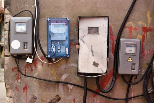
PLC and safety interlocks — e-motion limit at the top of stroke, anti-double-release latch, emergency-stop hardwired to the hoist-motor contactor — are landed on a dedicated panel with at least IP54 enclosure rating for outdoor service, and the drop-counter / energy-recorder is wired to a non-volatile logger so each impact's height and interval are auditable for the ground-improvement report. Cabling inside the mast is run in flexible chain (cable carrier), not free-hanging, because free-hanging leads snag on the ram guide shoes.
Skip wireless drop-counters as the primary record on a new install — they are useful for trend checks, but the wired encoder is the legal evidence of drop-height during acceptance. The instrumentation-side discipline (sensor selection, signal integrity, and PLC I/O assignment) for adjacent compaction-and-process machinery is mapped in the dynamic balancing machine spec reference, which covers transducer wiring on rotating equipment under shock load.
Phase 4 — Load Test, Drop Test, and Ground-Improvement Verification
Commissioning starts with a no-load hoist cycle (raise to 5 m, hold 60 s, lower under power) repeated three times to verify brake holding, drift, and encoder reading, then progresses to a 2-drop, 5-drop, 10-drop, and full-production drop-test sequence at progressively increasing drop heights up to the design value. Acceptance criteria I require before handing the rig to production: drop-height repeatability within ±2% of set-point across 10 consecutive drops, ram-mass verification on a calibrated weighbridge (or load cell) within ±1% of nameplate, and ground vibration at the nearest structure ≤ the limit set by the project geotech (commonly 5-25 mm/s peak particle velocity, scaled by distance and structure type).
Ground-improvement verification is done by pre- and post-compaction CPT or SPT at a grid spacing the geotech specifies (typically 5-10 m centers) and the test points must be located at the centers of the impact crater pattern, not on the craters' rims, because rim-zone soil is over-loosened by lateral shock and reads artificially low. A second-pass coverage map is plotted from the drop-counter log so missed points can be re-tamped.
Do not skip the 2-drop and 5-drop steps and go straight to full-height — early drops reveal cable-stretch, encoder zero-drift, and brake-heating that full-height drops mask until something fails. Where the compaction grid overlaps buried utilities, hand-dig or vacuum-excavate the first meter before tamping, because a 15 t ram at 20 m drop has been documented to fracture 100 mm clay pipe at depths above roughly 6 m.
Phase 5 — Documentation, Operator Handover, and Maintenance-Interval Set
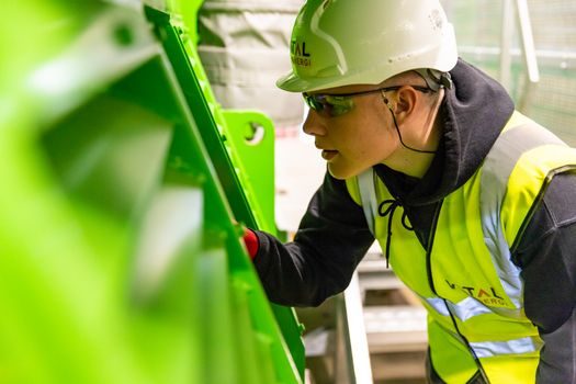
Final handover is a paper exercise first, machine exercise second: as-built mast-verticality record, hydraulic oil analysis report, PLC logic diagram with password access, drop-counter log file, and the signed-off geotech verification must all be in the handover folder before the operator takes the keys. OEM warranty is typically voided if commissioning is not signed-off within the stated window, and most OEMs require a 100-hour or 30-day post-commissioning inspection. [S4]
Maintenance intervals are set from this baseline: hoist-cable retirement at the OEM's cycle count (commonly 2,000-5,000 drops for 6×36 WS construction), hydraulic filter change at 250 hours or 90 days, trip-mechanism lubrication weekly, and full structural NDT of the mast and guide shoes at 10,000 drops or 12 months, whichever comes first. The maintenance-vs-replacement decision logic on adjacent wear components (bearings, packings, seals) is laid out in the thrust bearing selection map, which uses the same duty-cycle-then-spec approach.
Skip the documentation step and the project is exposed on three counts: the ground-improvement report cannot be signed off, the OEM warranty lapses, and the next site (if the rig relocates) has no baseline against which to verify alignment — meaning a known-good rig arrives at a new site as a known-unknown. Track the next handover via the 100-hour inspection report, the geotech sign-off, and the warranty registration date stamped by the OEM.
Spec-level background on the components involved: linear guide.