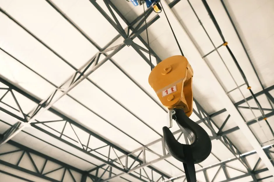
Tower crane type selection is driven by three site-bound variables: available footprint, vertical airspace, and the heaviest tip-load at the working radius, with OSHA 29 CFR 1926.1435(b)(5) requiring a plumb tolerance of at least 1:500 (1 inch in 40 feet) before any hammerhead, flat-top, luffing-jib, or self-erecting unit is committed to a foundation [S1].
Selection is no longer a single-crane call: BIM-based decision frameworks and MILP layout models now resolve the type, count, and jib-length combination that satisfies the heaviest prefabricated-component lift and the tightest site polygon, with 4D clash detection used to confirm safe overlap between adjacent cranes [S2][S8].
Four Functional Types and the Site Footprint That Forces Each Choice
The hammerhead, flat-top, luffing-jib, and mobile self-erecting configurations are not interchangeable: each is geometrically tied to the site polygon above the crane base, and the type is fixed by the first constraint that fails [S3][S7]. Hammerhead units carry the classic A-frame cat-head and deliver consistent lift capacity across their full horizontal jib, which makes them the default for open high-rise sites where maximum reach and tip-load dominate the specification [S3]. Flat-top cranes drop the A-frame and overhead tie-rods, reducing top-of-jib height by several meters; this geometry is preferred where multiple cranes must overlap on tight sites, since adjacent jibs can pass over each other without the cat-head collision risk [S3].
Luffing-jib cranes replace the fixed horizontal arm with a lattice jib that can be raised and lowered, which shortens the effective slewing radius and is the standard answer on congested urban sites, inside narrow footprints, or adjacent to existing structures that block a horizontal swing [S3][S7]. Mobile self-erecting units are smaller-capacity trailer-mounted machines with short setup times and minimal foundation work, and are matched to short-duration or relocatable lifts rather than sustained high-rise service [S3][S5]. Sany's published selection methodology breaks the process into four steps, define the lifts, evaluate the site, select the type, then verify clearances, which mirrors the order of precedence used in the academic AHP models [S2][S5].
Selection Criteria: Radius, Tip Load, Height, Airspace, and Foundation
Five quantitative inputs decide the type: maximum required radius, tip load at that radius, free-standing or tied height, available airspace above the jib, and the allowable foundation reaction [S3][S5]. On open sites with no overhead restriction, a hammerhead unit typically wins on raw jib length and lift capacity, while on a tight urban site with a neighbouring tower of equal or greater height, a luffing-jib unit is specified because its variable jib angle avoids the overswing sweep that a horizontal jib cannot clear [S7].
OSHA 29 CFR 1926.1435(b)(3) requires the foundation and structural supports to be designed by the manufacturer or a registered professional engineer, and 1926.1435(b)(7) requires a registered professional engineer to verify that the host structure can sustain the forces imposed through the braces and brace anchorages before any climbing operation [S1]. The same standard also restricts multiple fixed-jib (hammerhead) tower cranes on one jobsite such that no crane can come into contact with the structure of another, while still permitting jibs to pass over one another [S1]. Selection criteria for lifting performance such as jib length envelope, maximum and typical working loads, and reeving are detailed in the related tower crane design specifications reference.
Multi-Crane Layout: BIM, AHP, and MILP for Number, Type, and Position
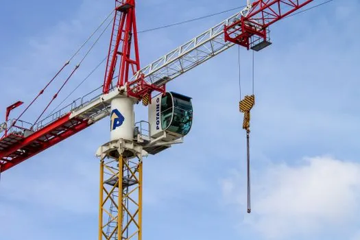
For sites that exceed a single crane's lifting envelope, a 2024 MDPI study on dual tower cranes for prefabricated-component lifts showed that a coordinated two-crane scheme can achieve more than twice the lifting efficiency of the same model operated as a single unit, and that value-engineering selection matched the shortest-lifting-time option only when cost was weighted into the objective [S4]. The framework used a genetic algorithm to first solve the feasible layout area, then optimised across three objectives, minimum cost, shortest total lifting time, and maximum value coefficient, before locking the count and position [S4].
A 2025 Emerald paper extends this to N-crane sites with a mixed-integer linear programming (MILP) model that simultaneously decides the number, type, and location of tower cranes plus the location of supply points, and verifies the result through 4D simulation for spatial conflicts [S8]. The underlying Marzouk and co-authors framework combines an AHP decision model for type selection, an optimisation model for count and position, and a 4D simulation model to detect clashing slewing envelopes, and is the reference academic baseline now cited across multi-crane planning studies [S2][S4][S8].
Comparison Matrix: Which Crane Type Fits Which Site
Comparing the four main types against four decision criteria produces a consistent engineering rule: hammerhead for open-site radius and tip-load, flat-top for overlapping multi-crane sites, luffing-jib for constrained or adjacent-structure sites, self-erecting for short-duration or relocatable lifts [S3][S7]. On airspace clearance, flat-top and self-erecting are lowest, luffing-jib is mid-range, and hammerhead is tallest; on maximum jib reach for a given class, hammerhead and flat-top lead, luffing-jib trades reach for swing compactness, and self-erecting sits well below the other three on both reach and capacity [S3].
On foundation demand, hammerhead and flat-top require the heaviest engineered bases, luffing-jib falls in the middle, and self-erecting typically needs only a minimal pad or outrigger setup [S3][S5]. On project duration, hammerhead and luffing-jib absorb their setup cost over long high-rise programmes, while self-erecting is the lower-cost answer for short or shifting sites [S3]. The 1:500 plumb tolerance and engineered foundation rules in 29 CFR 1926.1435 apply to every type, with mobile self-erecting units additionally subject to the 1926.1435(b)(2) exclusion-zone rule during erecting, climbing, and dismantling [S1].
Failure Modes and Constraints That Override the Type Decision

Three failure modes repeatedly force a re-spec: jib slewing into an adjacent structure, foundation reaction exceeding allowable ground bearing, and tip load at the maximum radius falling below the heaviest single pick [S2][S3]. Luffing-jib geometry exists specifically to neutralise the first failure mode on confined urban sites, and engineered foundations plus the 1:500 plumb rule exist to neutralise the second [S1][S7]. For prefabricated-component work, MDPI found that cost-optimised dual-crane layouts consistently outperformed time-optimised layouts on per-lift cost when the heaviest component and its supply yard sat at opposite ends of the site [S4].
Selection must also account for components that are described in our broader industrial equipment reference, which links structural envelope, drive type, and counterweight rules back into the site-layout calculation. Where the heaviest single pick exceeds the tip load at the required radius of any available single crane, the answer is rarely a bigger crane; the consistent answer across the BIM, AHP, and MILP studies is to add a second, smaller crane and rebalance the supply-yard geometry [S2][S4][S8].
Wind, Plumb, and Climbing Constraints Common to Every Type
Wind, plumb, and climbing rules apply uniformly and are enforced by OSHA 29 CFR 1926.1435 across hammerhead, flat-top, luffing-jib, and self-erecting alike: 1926.1435(b)(4)(iii) bars erection, climbing, or operation when wind exceeds the manufacturer's recommendation or, where the manufacturer is silent, the speed determined by a qualified person [S1]. The 1:500 plumb tolerance is the minimum legal default and is verified by a qualified person after each climb; tighter manufacturer tolerances override it wherever they exist [S1].
Inside climbing and top climbing both require a registered professional engineer to verify that the host structure can carry the forces imposed through the braces, brace anchorages, and supporting floors before each operation, and counterweight/ballast must be in place before any erecting, dismantling, or operating step [S1]. These constraints do not change between types, but they do set the minimum spec envelope inside which the type, jib length, and foundation choice must fit [S1][S3].
Sourcing, Standards, and What to Verify Before Committing
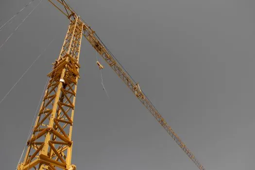
Two standards govern the safety floor for any tower crane type on a US jobsite: 29 CFR 1926 Subpart CC (the Cranes and Derricks in Construction standard) and, inside it, 29 CFR 1926.1435 for tower-crane-specific requirements covering erecting, climbing, dismantling, plumb tolerance, multi-crane jobsite rules, and counterweight/ballast [S1]. The structural and capacity claims used in selection should be traced to manufacturer type-approved documentation and to the registered professional engineer's foundation and tie-in design, not to marketing literature [S1][S3].
For project planning, the verifiable data inputs are the type-approved load chart at each jib length, the manufacturer's free-standing and tied height tables, the engineered foundation reaction, and the host-structure verification for any climbing tie; the planning outputs are the type, count, jib length, and positions consistent with the AHP/MILP frameworks, then confirmed by 4D clash simulation [S2][S4][S8]. The next trackable node on any multi-crane project is the registered professional engineer's foundation and tie-in sign-off, and the second is the 4D simulation output confirming non-contact between overlapping jibs on the proposed layout [S1][S8].
The underlying component specifications are covered under order picker, and dry type transformer.