
Maximum load moment, expressed in tonne-meters (t·m), is the governing metric for tower crane size classification: it equals the lifted weight multiplied by the load radius from the slewing axis, and it defines both structural strength and the rating of the load moment limiter [S2][S5].
A standard mid-size unit is rated at 300 t·m, meaning an 18 t (39,690 lb) maximum load at the jib root and roughly 10.1 t at 30 m radius, with a maximum unsupported height near 80 m and jib reach near 70 m [S2]. Across the global market, lifting capacity at maximum outreach spans 5-75 t depending on platform design, while overall lifting capacity typically sits in the 20-100 t band for high-rise construction [S6][S1].
Load Moment as the Governing Spec
Load moment (weight × radius) is the overturning moment the crane must resist, and it scales linearly with jib reach: the larger the radius, the greater the moment for the same load [S1]. This is why every modern tower crane carries a load moment indicator or rated capacity indicator that warns the operator before the moment rating is exceeded [S4]. Two limit switches enforce the envelope: a maximum load switch on the hoist cable and a load moment switch that senses jib deflection through the cat-head assembly in the slewing unit [S2].
For selection, a crane is not bought for its maximum tip capacity but for its moment rating at the working radius, which is why Liftmoore-style guidance treats weight, radius, and cycle frequency as the three primary inputs [S5]. The relationship is concrete: a 10,000 lb crane with a 72,000 ft·lb moment rating has a maximum working radius of 7.2 ft (72,000 / 10,000), and the same arithmetic in metric units gives a 10 t load at 30 m for a 300 t·m crane [S5][S2].
Size Classes by Tonne-Meter Band
Practical sizing bands, derived from typical OEM data: small (city, low-rise) tower cranes cover roughly 40-100 t·m, commonly delivering 4-8 t at the jib tip with radii up to 40-50 m; mid-range (standard high-rise) units cluster at 100-300 t·m, typified by the 300 t·m / 18 t benchmark with 70 m reach [S2][S6]. Heavy-duty and super-tower classes start above 300 t·m and extend to roughly 800-1,000 t·m for power-plant, bridge, and supertall-building applications where a single lift can demand 50-75 t at the tip [S1][S6].
The capacity spread at full outreach is wide because platform architecture matters: flat-top, cat-head, and luffing-jib designs each trade moment for reach and hook height differently, and rotary versus non-rotary base frames change how much of the moment is reacted into the foundation [S6]. Counterweight also participates directly in the moment equation, with 16.3-20 t of ballast standard on a 300 t·m class machine [S2].
Selection Criteria Beyond the Moment Number
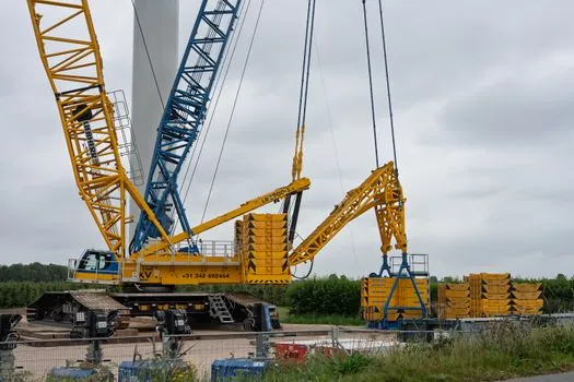
Three engineering quantities decide the class: required tip load at maximum working radius, maximum tip load close to the mast, and free-standing hook height before the first tie-in to the structure. The first two define the moment envelope, while free-standing height drives whether a climbing or tie-in configuration is needed at all [S2][S3]. European designs are calculated to EN 14439 under Machinery Directive 2006/42/EC for supporting-structure loads, a different load-combination regime than the Eurocodes, and FEM guidance treats foundation, corner, and anchor reactions as separate load cases [S3].
Operating envelope is also constrained by wind, ground slope, and attachment mass: a 1 t electromagnet on a 50 t crane drops net capacity to 49 t before the moment limit is even checked, and load charts must be re-read for any jib configuration, reeving, or outrigger change [S1][S4]. A spec-driven comparison of small, mid, and heavy classes against four criteria is summarised below:
Class comparison: small (40-100 t·m), tip load 4-8 t, max reach 40-50 m, free-standing height ~30-40 m, foundation reaction low; mid (100-300 t·m), tip load 8-18 t, max reach 60-70 m, free-standing height 40-60 m, foundation reaction moderate; heavy (>300 t·m, up to ~1,000 t·m), tip load 18-75 t, max reach 70-80+ m, free-standing height 60-80+ m, foundation reaction high and often requiring piled supports [S1][S2][S6].
Safety Devices and Standards Behind the Moment Rating
EN 14439 is the harmonised European standard for tower crane safety, giving presumption of conformity to Machinery Directive 2006/42/EC, while FEM 1.001 and the FEM Product Group position paper govern load combinations on supporting structures separately from the Eurocodes [S3]. The position paper breaks supporting loads into three families, foundation reactions, corner loads on undercarriage or cross foundations, and anchoring loads for climbing configurations, each derived from dead weight, hoist load, and inertia from slewing, trolleying, and hoisting drives [S3].
Onboard, the load moment limiter is the practical enforcement of the rating: it tracks jib deflection at the cat-head and trips motion when the calculated moment approaches the structural limit, and the maximum load switch independently caps hoist pull at the single-line rating (for example, 18 t on a 300 t·m class crane) [S2]. For specifiers cross-checking machine ratings, mast-section sizing for a given class is detailed in this mast-section spec decision guide, and the role of a properly rated tower crane in the lift plan is the starting reference point. Auxiliary signalling on the slewing platform, including signal tower lights for status and wind alarms, is typically tied into the same safety PLC that hosts the load moment indicator.
Failure Modes and Common Mis-Specs

The dominant failure mode is overturning from moment overload, not cable or hook failure, and the load moment limiter exists precisely because operators historically pushed the jib out at the maximum charted tip load without checking the moment [S1][S2]. A second recurring mis-spec is buying on maximum lift capacity instead of moment rating: a 50 t crane at 5 m radius and a 10 t crane at 25 m radius can share the same moment class but suit entirely different sites, and choosing the wrong one leads to either a tip-over risk or a chronically under-used machine [S5].
Third, wind, ground slope, and reeving changes are routinely ignored in the field; a load chart is configuration-specific, and a chart valid over the rear at 360° is not the same as a chart valid only over the front with outriggers down [S4]. Finally, attachment mass must be deducted from chart capacity before the moment is even evaluated, so any jib extension, lifting beam, or magnet permanently lowers the working envelope regardless of the rated class [S1][S4].
Who Size Classes Are For, and Who They Are Not For
These classes are for specifiers, site planners, and structural engineers who need to match a lift plan to a foundation design and to EN 14439 / FEM supporting-structure calculations, not for end-of-day hoist decisions on a single lift [S3]. A 40-100 t·m class fits residential and low-rise commercial work where reach and tip load are modest; the 100-300 t·m mid band covers most high-rise cores; the >300 t·m heavy class is for supertall towers, bridge pylons, and energy-sector sites [S1][S6].
These classes are not a substitute for the OEM load chart on the actual machine in the cab, which remains the controlling document for any individual lift [S4]. For mobile pick-and-carry work, truck crane moment ratings, not tower-crane t·m, govern, and the two equipment families should not be cross-compared on the same chart. A useful cross-reference for adjacent machine-room decisions is this gas-alarm channel sizing guide, which applies to operator-cab environment monitoring rather than moment selection.
Trackable signals for the next planning cycle: EN 14439 amendment cycle outcomes and any revision to FEM 1.001 load-combination factors, plus OEM disclosures of the next-generation >800 t·m platforms entering the supertall segment. For an adjacent drivetrain decision often made at the same time as crane selection, see the screw-conveyor drive selection guide.
The underlying component specifications are covered under electronic load.