
Outrigger span and stability rating are mechanically linked: a truck-mounted crane with outriggers only partially extended can lose more than half of its published load chart before any load leaves the hook. Stability testing per SAE J765 is conducted at 118% of maximum capacity, equivalent to 85% of the actual tipping load, around the full 360° arc of the truck [S2].
More than 50% of mobile crane failures trace back to improper outrigger use, and roughly 54% of crane upsets happen when the outriggers are not fully extended [S1]. The physics is unforgiving: the rated capacity on the decal assumes the published footprint, and shrinking that footprint shrinks the lift chart in a non-linear way.
How Outrigger Span Becomes the Stability Number
Outriggers are support structures that lift the wheels of the crane or vehicle off the ground to create a wider, more stable base [S5]. Each outrigger assembly is built from three components: a horizontal beam that extends the support away from the chassis, a vertical hydraulic jack that transfers load, and a support pad (or float) that distributes pressure to the soil [S5]. Extending the beams increases the tip-over resistance roughly with the square of the half-span, so a 1.4× wider footprint can roughly double the moment arm available before the load vector exits the stability polygon.
OSHA 29 CFR 1910.180(c)(1) governs vehicle-mounted crane stability on the service-crane side, while 29 CFR 1926.1402 ("Ground conditions") requires that equipment must not be assembled or used unless ground conditions are firm, drained, and graded to a sufficient extent so that, in conjunction with supporting materials, the equipment manufacturer's specifications for adequate support can be met [S4]. Two distinct CFR sections therefore control the same lift: one for tipping stability, one for ground bearing.
Stability Test Procedure and the 118% Rule
Per SAE J765, the vehicle stability test is performed on a hard, level surface within +/- 1% grade, with the truck PTO engaged and hydraulic oil warmed for 5 minutes, outriggers extended to full horizontal, and jack legs deployed until the outrigger cross-tube tops out (unloading the rear tires but not lifting them clear of the ground) [S2]. The crane is then elevated to 0-15° boom angle and rotated to the most adverse "B" position to pick up a load equal to 118% of rated capacity.
That load is lifted only about 6 inches off the ground, the lifting device is removed, and the crane is slowly rotated through its entire operational range. If 100% stability is maintained around the full arc, a green stability decal is applied; otherwise, the reduced percentage is written into the alternate two-zone decal in the affected arcs [S2]. OSHA explicitly allows a service crane to lift an outrigger leg or wheel(s) off the ground during this test and still consider the truck stable, provided the truck does not tip [S2].
Ground Bearing Pressure: The Soil Side of the Equation
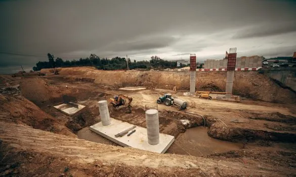
Full-span outriggers mean nothing if the soil under the float pad cannot carry the point load. Typical allowable ground bearing pressures run from 500-1,000 psf for soft or wet soil up to 10,000+ psf for solid rock or concrete, with compacted gravel rated around 4,000-6,000 psf and firm clay at roughly 2,000-3,000 psf [S1]. Float pad sizing is the variable that bridges span and soil: the same outrigger reaction force divided across a 24"×24" pad (4 ft²) versus a 36"×36" pad (9 ft²) cuts bearing pressure by more than half.
Outrigger pads must not be used to bridge gaps or span voids, and they must be selected based on equipment type, soil conditions, and lift type [S4]. A pad that is too small pushes the soil past its bearing limit, the float punches in, and the crane begins to lean. The level tolerance and grade percentage from the manufacturer's chart must be respected; if level is wrong, lifting capacity is reduced even before ground bearing is considered [S4].
Outrigger Geometry: H-Style vs A-Frame
Two outrigger geometries dominate the truck crane market. H-style outriggers extend straight out from the crane and then straight down to the ground, giving the maximum horizontal half-span and the most rectangular stability polygon [S5]. A-frame outriggers extend out from the crane at an angle, more common on mini crawler cranes, trading some horizontal reach for a smaller stowed envelope and lighter beam structure [S5].
Variable outriggers sit on top of these geometries as an adjustment layer: they are retractable extensions that can be pinned at multiple intermediate spans, letting the operator shorten the footprint to clear jobsite obstacles at the cost of a derated load chart. On a typical four-position variable outrigger, the published capacity at the half-span and quarter-span positions can drop to roughly 50-70% of full-span capacity, with the over-rear arc usually rated higher than the over-side arc because of where the counterweight sits in plan view.
Lifting Over the Side vs Over the Rear

Lifting over the side is the least stable location for most truck cranes, because the outrigger half-span on the lift side is the moment arm resisting the load, and the chassis mass on the opposite side is the only counterweight [S3]. The standard mitigation is to position the crane so the initial lift is over the rear or over a corner with the maximum diagonal outrigger span engaged, then rotate the load into place without slewing through the weakest arc.
For a boom configuration decision that interacts with outrigger span, longer boom extensions raise the load higher and move the lift vector farther from the truck's centerline, which steepens the stability demand on the outriggers. A counterweight layout that pairs with the chosen span is the second adjustment available within the OEM's published chart; counterweights shift the center of mass back over the footprint, while extendable outriggers make the footprint bigger, and the two are typically traded off against each other within transport weight limits [S4].
Selection Criteria: Match Span to Lift, Not to Pad Space
Specification discipline for a truck crane outrigger package comes down to four numbers: maximum full-span half-width in meters, partial-span capacity derate (typically 30-50% loss at quarter-span), maximum allowable ground bearing pressure in psf or kPa, and the level tolerance in percent grade. The OEM load chart encodes all four; the operator's job is to confirm that the actual setup matches the chart line being used. [S2]
For most general construction lifts on compacted gravel or asphalt, a standard H-style outrigger at full span with 24" square floats is the baseline. For confined urban sites with soft subgrade, specify variable outriggers with documented quarter-span capacity, oversized 36" floats, and crane mats rated for the calculated point load. For utility and aerial work where the truck must work on slab decks with documented kPa limits, half-span operation with engineered load-spreader plates is usually the only safe option. In every case, the rule is the same: a shorter outrigger span and a softer soil both subtract from the published chart, and the larger of the two derates governs.
Track for the next update: OEM revisions to SAE J765 (currently the cited stability test code) and any 29 CFR 1926.1402 amendments affecting ground-conditions language for outrigger-supported mobile cranes.
Detailed specification references: dump truck.