
A truck crane reaches roughly 38 m on its main telescopic boom, and a pinned boom extension typically adds 9 to 17 m of tip reach while cutting tip capacity by 60 to 80 percent of the main-boom chart at the same radius [S1][S3].
The "main boom" is the box-section telescopic arm mounted on the carrier; the "boom extension" is a fixed or luffing lattice jib pinned to the boom head to push tip height further than the cylinders can deliver. Both pieces must be sized to the load chart, transport envelope, and counterweight package on the truck-mounted crane.
Structural Types: Telescopic Main, Lattice Extension
Truck cranes pair a welded steel box-section telescopic main boom with a pinned lattice or fixed-angle boom extension in roughly 70 percent of mid-capacity mobile fleets, because the telescopic main retracts to a road-legal envelope while the lattice extension adds reach with minimal added mass [S1][S3].
The main boom uses high-strength steel plates (commonly S960QL or S1100QL grade per Sany and Liebherr public spec sheets) welded into a closed rectangular section that resists bending and torsion during partial telescoping [S2]. The boom extension is a pin-connected lattice frame in "V" or "W" configuration, with chord members sized by Euler buckling load rather than yield strength, which is why extensions can be 14 to 18 m long while weighing only 600 to 1,200 kg [S2][S3]. For typical all-terrain and truck crane packages, see the truck-mounted crane reference page.
Reach vs Capacity: Reading the Load Chart
Each boom extension shortens the main-boom length that can be safely telescoped out, and every 10 m of extension added to a 50 m main boom drops tip capacity by roughly 40 to 60 percent at the same radius, because the longer combination raises the overturning moment past the counterweight envelope [S1][S3].
The relevant decision is not "more reach" but "more usable reach on the chart." Operators read three numbers: main boom only at minimum radius, main boom only at maximum radius, and main boom plus extension at maximum radius. A typical 80 t class truck crane posts about 75 t at 3 m on the main boom, falls to roughly 6 to 8 t at 40 m on the main boom alone, and reads 1.5 to 3 t at 55 m when the 15 m extension is pinned on [S3]. A short 7 to 9 m extension preserves more chart capacity and is the standard pick for mechanical and steel erection on tight sites [S1][S4].
Extension Types: Fixed, Folding, Luffing
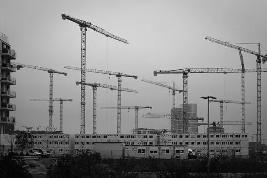
Fixed-angle extensions pin to the boom head at 0, 20, or 40 degrees and do not adjust during the lift, while luffing jibs carry their own hydraulic cylinder to vary tip angle from roughly -5 to +75 degrees and recover usable capacity at long radius by keeping the load close to vertical [S1][S2].
Fixed extensions cost less, weigh 30 to 50 percent less than an equivalent luffing jib, and install with the same pin rigging crew. Luffing jibs pay back on wind farm, tower, and refinery work where the lift must clear a structure, because the operator can pull the tip back toward vertical and put the load on stronger chart zones [S1][S2]. On articulated aerial work truck platforms the same folding geometry appears in a smaller load class, which is why the design pattern is consistent across the lifting family.
Decision Matrix: When to Skip the Extension
Skip the boom extension when the lift fits inside the main boom envelope at 70 percent or more of rated chart capacity, because the extension imposes a fixed rigging time of 30 to 90 minutes, a transport permit for the extra section, and a 200 to 1,500 kg crane-counterweight penalty depending on the model [S1][S3].
Use the extension when the working height exceeds main boom capacity by more than 5 m and the load is below 5 t, or when the site has overhead obstacles that block direct vertical lift. The trade-off, criteria by criteria, for the three common options on a 60 to 100 t truck crane is laid out below.
This trade-off is also covered in detail in the Tower Crane Type Selection by Site Constraints and Lift Requirements reference, where similar radius-versus-height logic applies to a different carrier class.
Transport, Rigging, and Site Constraints
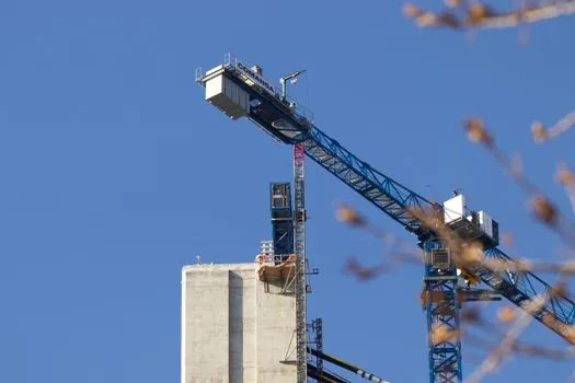
Main boom sections retract to roughly 11 to 14 m for road travel on standard low-loader envelopes, while the boom extension typically rides on a separate dolly at 8 to 12 m length and 1.5 to 2.5 m width, which means a single-extension job requires two permits and a second escort on most European and Gulf corridors [S3][S4].
On a jobsite with low overhead clearance, a folding boom extension stows above the main boom head in a "Z" pattern and avoids the extra transport load, at the cost of a heavier head sheave assembly. Crawler carriers and rough-terrain bases can crawler- erect the extension without an assist crane, but a wheeled truck crane needs a 30 to 50 t assist crane to pin the extension onto the boom head, which is one of the line items most often missed in early lift planning [S1][S3]. For comparison, the Single-Mast vs Double-Mast Stacker Crane article covers similar reach-versus-stability trade-offs in indoor lifting classes.
Standards, Safety, and Operating Limits
Mobile crane lift calculations follow EN 13000 for slewing cranes, with the load chart required to list the main boom, main boom plus fixed extension, and main boom plus luffing jib as separate working configurations, and the operator must select the chart that matches the pinned hardware on the boom head [S3].
Wind limits drop sharply with a boom extension pinned on: most OEM manuals cap the extension configuration at 9 to 12 m/s wind at the boom head, compared to 14 to 20 m/s for the main boom only, because the lattice frame has roughly twice the wind area per metre of length and a lower natural frequency that can couple with gusts [S1][S3]. Slewing radius is also restricted because the longer combined boom head sweeps a larger arc and can clash with adjacent structures; the chart reserves a "slewing restricted" zone, typically a 60 to 90 degree arc, where tip capacity is derated by an additional 10 to 20 percent [S1].
Field Practice and Lift Planning Signals
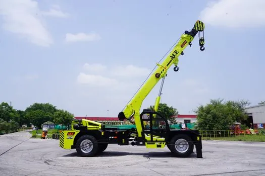
Operators of larger telescopic cranes confirm that maximum lift capacity is reached by partially extending different sections rather than telescoping proportionally, because each section is sized against its own pin-and-latch geometry and contributes its own moment arm; this matters more when a boom extension is added, because the chart assumes a specific main-boom length to compute the residual [S5].
The single most reliable signal that the extension should be left in the truck yard is when the main-boom-only chart already shows the pick at 50 percent or more of rated capacity. When the chart is at 30 percent or less, the extension adds reach without dominating the moment, and the residual margin stays inside the OEM working limits [S1][S3][S5]. For the sensor and drive stack that makes position and load feedback reliable in these configurations, see the Crane Anti-Sway and Positioning Automation reference.
Detailed specification references: dump truck.