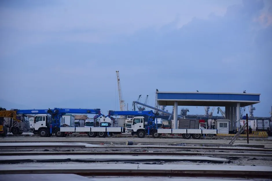
A truck crane's lift chart is built on two physical inputs, the outrigger span (or pad extension) and the counterweight mass, and the load chart published by the manufacturer is the only document that legally binds those two inputs to a permitted load at a given radius [S5]. Mis-handling either input collapses the stability polygon: more than 50% of mobile crane failures are attributed to improper outrigger use, and roughly 54% of crane upsets occur when the jacks are not fully extended [S1].
On a typical hydraulic boom truck crane the outriggers are four beams, two front and two rear, that lift the carrier off the tyres and transfer the entire machine weight, plus the suspended load moment, into the ground through float pads (also called outrigger float, base plates, or load spreaders) [S3]. The counterweight slab is a separate, removable mass bolted to the superstructure rear; it generates the restoring moment that opposes the load moment created by the boom and hook [S4]. Both systems must be matched: a heavier counterweight allows a longer load moment, but only if the outrigger polygon is large enough to keep the resultant ground reaction inside the pad footprint [S3].
Stability polygon, ground bearing pressure, and the four input variables
The outriggers define a virtual rectangle (or square, for H-style outriggers) on the ground; any load the crane lifts must keep the combined centre of gravity of the upper structure, counterweight, boom, and hook load projected vertically inside that rectangle, otherwise the crane tips toward the load [S3]. The four variables an operator controls are outrigger extension distance, outrigger pad area, counterweight mass, and outrigger jack engagement, and each of them is a row in the load chart, not a free parameter [S5].
Ground bearing pressure is the next constraint once the polygon is set: solid rock or concrete tolerates 10,000+ psf, compacted gravel 4,000-6,000 psf, firm clay 2,000-3,000 psf, and soft or wet soil drops to 500-1,000 psf [S1]. The OEM chart assumes a uniform, near-rigid surface, so the engineer in the field has to back-calculate pad size from measured soil capacity before the chart number is trusted; undersized pads on soft ground effectively shrink the stability rectangle and produce the rearward overturning failure mode the Safe Work Australia guide flags as the classic "boom-up, pad not blocked" upset [S3].
Counterweight mass, swing radius, and the inverse-capacity curve
Maximum lifting capacity drops sharply as working radius grows, and it is the moment balance, not the boom's raw strength, that usually governs [S5]. On the load chart, capacity is plotted on the vertical axis against radius on the horizontal axis, and each curve corresponds to a fixed combination of boom length, outrigger span, and counterweight mass; changing the counterweight from, say, a 4 t slab to a 7 t slab re-draws the curve upward at long radius, because the heavier tail mass increases the restoring moment that resists forward tip [S4][S5].
Counterweight selection is a back-over risk as well as a forward-tip risk: if the counterweight is too heavy for the boom length, or if the crane is on a slope with the boom elevated, the rear outrigger can lift and the machine overturns backward, and Safe Work Australia lists inadequate timbers under the rear outrigger pad, plus outriggers not extended, as the two dominant causes of that mode [S3]. Operators therefore match counterweight to boom length, never to hook load alone, and the load chart's "counterweight installation position" row encodes that match [S5].
Outrigger configurations compared: H-style, X-style, and single-jack
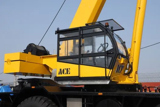
Outrigger geometry is not a single design: most modern truck cranes use H-style outriggers, with beams that extend horizontally and jacks at each corner, giving the largest rectangular footprint and the highest published chart capacities [S1]. X-style outriggers, where the beams cross under the carrier, save stowed length and are common on smaller truck cranes, but the pad-to-pad span in the travel direction is shorter, so the chart capacities at long radius are correspondingly reduced.
Single-jack or A-frame outriggers (one beam per corner, jack at the tip) are the lightest configuration and typical of pick-and-carry or city-crane builds; the Safe Work Australia guide treats single-jack machines as the most sensitive to ground slope and pad blocking because the polygon is narrower in one axis [S3]. Comparing the three on the four decision criteria below makes the trade-off explicit:
H-style vs X-style vs single-jack A-frame outrigger layouts, on footprint area, chart capacity at long radius, ground preparation effort, and rear-tip margin: H-style wins on footprint area and long-radius capacity, requires full four-pad timber blocking, and gives the largest rear-tip margin because the rear pad sits furthest behind the slewing centre. X-style sits in the middle on every criterion, and is the common compromise on 25-50 t truck cranes where roadable length matters. Single-jack A-frame has the smallest footprint, the lowest long-radius chart number, the lowest pad-prep effort, and the narrowest rear-tip margin, which is why it is restricted on lifting above 75% of rated capacity in most critical-lift definitions.
Load chart reading sequence and the critical-lift threshold
The standard reading sequence is: confirm the crane model and configuration row, read the working radius (horizontal distance from the slewing centre, or outrigger centre, to the hook) off the site, find the capacity at that radius for the installed boom length and counterweight mass, then subtract rigging weight to get the net hook allowance [S2][S5]. A worked example: 25 t listed at a 50 ft radius with full counterweight and full outriggers, minus 1 t of rigging, leaves 24 t as the permitted hook load, and that arithmetic must be redone for any change in radius, boom length, or counterweight setting [S2].
The 75% threshold is the widely used critical-lift cut-off: any lift above 75% of the chart capacity, any lift over an active work area, and any lift in a restricted space is treated as a critical lift requiring formal engineering review, a documented lift plan, and a separate stability check beyond the published chart [S2]. Outrigger span and counterweight mass on the chart are valid only for the ground condition the OEM assumed; soft ground or unblocked pads require a derate that the chart does not print, so the derate is the lift planner's responsibility [S1][S3].
Failure modes: forward tip, backward tip, and the soft-pad sink
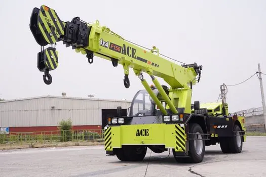
Three failure modes dominate the incident record. Forward tip is the most common and is the one the 54% "outriggers not fully extended" statistic captures, because a partially retracted outrigger shifts the front pad reaction point inward, shrinks the stability rectangle on the load side, and any long-radius lift inside the cab's normal chart can still tip the machine [S1][S3]. Backward tip is the second mode and is governed by counterweight mass versus boom angle, pad condition under the rear outrigger, and ground slope; it is the failure mode most associated with travel-up-slope operations on rough terrain cranes [S3].
The third mode is pad punch-through, which is not a stability calculation failure in the usual sense but a ground bearing failure: the pad sinks until the carrier side or a non-jack point contacts the ground, after which the chart's assumed rectangle no longer exists and the crane rolls [S1]. Blocking the jack on timber pads sized for the measured soil is the only practical mitigation, and most OEM manuals list minimum timber dimensions (commonly 24 in x 24 in or larger for 50 t+ machines) as a setup pre-condition, not a recommendation [S1].
Reading the chart: what each row actually controls
Load charts are configuration matrices, and the five core elements are maximum lifting capacity, lifting radius, boom length, outrigger position, and counterweight configuration [S5]. Outrigger position is normally encoded as "full" or "half" extension, and counterweight configuration as a mass figure (e.g. 4 t, 7 t, 12 t) plus its installation position (rear of superstructure, or rear of carrier) [S5]. Operators must read the matching row, not the nearest row, because a half-extended outrigger can cut chart capacity by 30-50% at long radius on most truck cranes in the 30-80 t class, and a lighter counterweight has a similar effect at the top of the radius range [S1][S5].
Boom length interacts with counterweight and outrigger span through the load moment: a longer boom reduces structural rigidity and raises the moment about the slewing centre, so the same counterweight that supports a short-boom chart curve will under-support the long-boom curve at the same radius [S5]. This is the reason chart pages are usually laid out as a grid of boom length rows and counterweight columns, and the reason the working radius must be measured, not estimated, before the chart is read [S2][S5].
Where outrigger and counterweight design is heading in late 2026
OEMs continue to expand the number of counterweight "slices" offered per crane model, with 3-5 staged counterweight options becoming standard on 50-100 t truck cranes, and variable outrigger span (3-position rather than 2-position jacks) now appearing on premium models [S5]. The trend is driven by lift planners who want narrower chart cells: a 3-position outrigger combined with 4-5 counterweight stages gives 12-15 distinct chart cells per boom length, instead of the 4 cells that a 2-position jack and 2-stage counterweight machine produces [S5].
Two trackable signals to watch into the rest of 2026: first, more OEM load charts are being delivered as interactive digital tables (web and tablet) rather than printed plates, which removes the "wrong row read" error that contributes to the 50% outrigger-misuse failure rate [S1][S5]; second, telematics-based outrigger-state monitoring (extension sensors, jack pressure sensors) is being offered as a retrofit on older truck cranes, with the explicit goal of preventing partial-extension lift attempts before they happen [S1].
For the relevant spec sheets and selection criteria, see truck mounted crane, checking and testing apparatus, and construction machinery and equipment.
This topic is covered further in 2 MW and 3 MW Diesel Generator Lead Times in 2026: Factory Quotas, Commissioning.