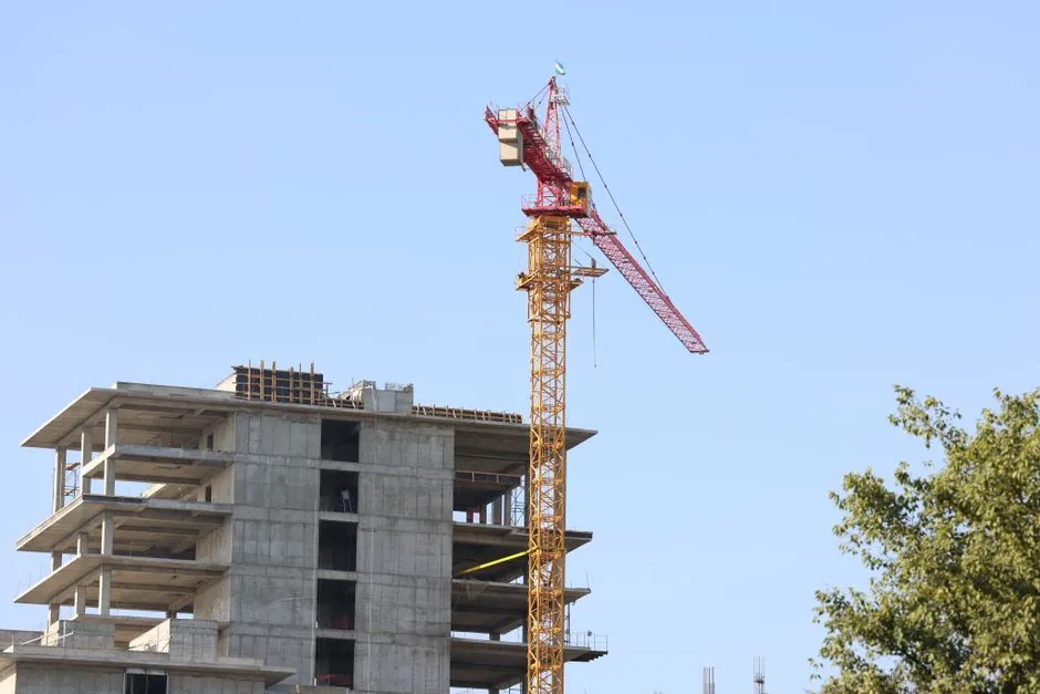
A placing boom reach diagram plots four numbers from the boom's turret pivot: vertical reach, horizontal reach, depth reach (how far the boom can drop below the mounting deck), and unfolding height, and the gap between rated and effective reach is set by outrigger footprint, climb geometry, and tip-hose clearance [S1][S2].
For a Spider-class placing boom the chart commonly shows 59 ft vertical, 52 ft 5 in horizontal, 32 ft 8 in depth, and 13 ft unfolding height; a Mini Placer sits at 60 ft / 60 ft / 26 ft / 18 ft 10 in across the same four axes [S1]. For truck-mounted boom pumps the envelope scales from a 20 m class (65 ft vertical, 55 ft horizontal) to a 65 m class (210 ft vertical, 195 ft horizontal) in 5-section RZ configurations [S2][S5].
The four axes every chart exposes
Vertical reach is the height of the boom tip above the mounting plane, measured with the boom folded straight up; horizontal reach is the radius from the turret to the tip with the boom laid out parallel to the ground, so a 47 m RZ folds out to 154 ft vertical and 135 ft horizontal from the same truck [S2]. Depth reach, the value most contractors miss, is how far the tip can be lowered below the boom's mounting deck, and it governs negative-slope pours such as basement mats, pit walls, and pool shells; the Spider at 32 ft 8 in and the Mini Placer at 26 ft both clear typical residential pool depths without re-rigging [S1].
Unfolding height is the free air the boom needs to open before it can extend, and it is the single number that decides whether the boom can deploy under an existing slab, a bridge soffit, or a parking deck header; the Spider's 13 ft envelope lets it work inside a single-storey structure, while the Mini Placer at 18 ft 10 in needs a taller bay or an outdoor pad [S1]. Read together, the four axes define a 3-D working envelope; the pour point must sit inside it, with margin for the tip hose, the operator's sight line, and any structure the boom has to clear on the way out.
Rated reach versus effective reach
Advertised reach is measured from the turret at the truck centreline, so the outrigger footprint, the setup position the site allows, and the geometry of getting over an obstacle and down to the forms all subtract from the brochure number [S5]. Outrigger spread commonly eats a 25 to 40 ft ring around the truck, and that ring has to sit on ground firm enough to hold the reaction loads without shoring, so a 65 m pump with 210 ft of vertical reach may only deliver 180 ft of effective reach on a constrained urban lot [S5].
The climb is the other silent killer: height spent going up is length not available going out, and reaching over a two-storey house before tipping down into a backyard pool can consume 30 to 40 ft of horizontal envelope that a flat-field chart would otherwise show as available [S5]. ACPA's separate-placing-boom section reinforces the same point from the operator side, requiring that the boom be deployed only on ground that has been inspected for slope, bearing capacity, and overhead conductors before any section is unfolded [S4][S8].
Reading obstacles and overhead conductors on the chart
Before trusting any reach number, the diagram should be overlaid on the site plan with three exclusion zones drawn in: outrigger pads, overhead power line clearance, and the climb-and-tip path. Queensland's concrete pumping code of practice 2019 requires the PCBU to inspect for overhead powerlines before setup and to maintain the regulator-mandated exclusion distance around energised conductors, which on typical distribution voltages means treating 20 ft of vertical and horizontal clearance as the working floor around any line crossing the boom path [S5][S8].
On the depth axis, the chart should also be checked against below-grade obstructions: a basement excavation with a soil-nail wall or a secant-pile perimeter takes the truck back from the edge by the stand-off distance the shoring designer requires, and that stand-off is paid for out of horizontal reach before the boom even opens. The Mini Placer's 26 ft depth reach only matters if the truck can park close enough to the excavation for 26 ft of negative drop to actually reach the formation level [S1].
Matching boom class to pour geometry
Small booms in the 20 to 28 m class (65 to 90 ft vertical) handle residential slabs, driveways, and footings on tight lots where a larger truck cannot deploy outriggers; mid-size 32 to 38 m pumps deliver roughly 120 ft vertical and 110 ft horizontal, the workhorse envelope that clears a two-storey home and still reaches a backyard pool deck from a street setup [S2][S5]. Large 42 to 47 m units cover deep lots and mid-rise decks where every avoided reposition saves an hour of placing-boom or boom-pump time on the pour, while 52 m and above are reserved for pours where a single setup replaces two or three smaller-boom moves [S5].
For ground-level work beyond the truck's reach envelope, a line pump trades height for horizontal hose run, with practical runs of several hundred feet when the mix design is sized for line pressure and the hose path is laid out without sharp bends; this is the same geometry problem the reach chart solves, just with the diagram unrolled along the ground instead of folded into a vertical envelope [S5]. A useful sanity check is to compare the rated pumping output against the delivery line: the BSA 2110 stationary pump pairs 111 yd³/h output with 3,190 psi delivery pressure, so a 5 in delivery line on a 63 m RZ boom can sustain 180 m³/h at full reach only because the pump and the line are matched, not because the boom is taller [S1][S2].
Pre-pour checks the diagram forces you to do

Five site numbers have to be on the table before the reach chart is interpreted: the pour point elevation relative to the truck's planned parking surface, the horizontal distance from the parking surface to the pour point, the maximum height of any obstacle between them, the depth below the truck's mounting deck the boom tip must reach, and the clear envelope above the truck needed to unfold the boom [S5]. With those five numbers drawn on the plan, the reach diagram becomes a pass/fail overlay: the pour point must sit inside the vertical/horizontal/depth envelope with margin, the obstacle's silhouette must sit below the boom's climb path, and the unfolding height must fit under any overhead structure.
ACPA's certified-operator study guide adds the operational layer: the radio between the operator and the pour-side spotter has to be tested before anyone climbs the placing boom, the pipeline has to be inspected end-to-end for wear clamps and gaskets, and the operator has to confirm that the boom is on level, compacted ground with all outriggers fully deployed before the first section is unfolded [S4]. A reach diagram is only as reliable as the ground beneath the outrigger pads and the air clearance above the tip, so the chart reading and the site walk have to happen on the same afternoon, not on different days [S4][S8].
Comparison: reach envelopes across three common boom classes
Lining up a Spider placing boom, a 47 m RZ truck-mounted boom pump, and a 65 m RZ boom pump on four decision criteria shows where each one earns its keep: the Spider at 59 ft / 52 ft 5 in / 32 ft 8 in / 13 ft unfolding height is the only one that fits inside an existing structure and pours a pool shell in a single setup [S1]. The 47 m RZ trades unfolding height for raw envelope, reaching 154 ft vertical and 135 ft horizontal from a street setup but needing roughly 30 ft of clear air to deploy, so it dominates mid-rise decks and large foundations [S2]. The 65 m RZ stretches to 210 ft vertical and 195 ft horizontal with a full 5-section Z-fold, but the outrigger spread and the truck length (a 2110-class mounted pump is 35 ft 4 in long and 8 ft 2 in wide) push it onto sites with genuine setup room, and it is the right answer only when fewer repositionings on a stadium or high-rise pour pay back the mobilisation cost [S1][S2].
For a working engineer sizing the pour, the decision is rarely which boom is longest, it is which boom's effective envelope matches the site after outriggers, climb, and tip hose are subtracted, and that is exactly what a properly read reach diagram is for. The same geometry logic that drives a placing-boom chart also drives adjacent specification decisions, from the precast vs pour-in-place deck choice sitting under the boom to the driven-foundation selection sitting beneath the outrigger pads, because the boom only places what the structure below can carry.
Two trackable signals close the loop: first, watch whether your rental house publishes reach charts that include depth reach and unfolding height alongside the headline vertical and horizontal numbers, since a chart that omits depth reach is hiding the basement-mat failure mode, and the Spider and Mini Placer sheets are the current reference for what a complete four-axis chart should look like [S1]. Second, walk the site with the printed chart overlaid on the plan and mark the actual outrigger pads, the climb path, and the tip-hose swing radius before signing the setup ticket; if the pour point falls outside the trimmed envelope, the answer is a smaller boom with a different parking position, not a bigger boom on the same pad [S4][S5].
Detailed specification references: reach truck, pressure transmitter, and flow meter.