
Two-hand control for electrical work is a safeguarding device, not a control relay: it requires concurrent, timed actuation of two separated actuators so that the operator's hands are physically committed outside the hazard zone during the dangerous motion [S2].
For an electrical-maintenance task (energising a test rig, starting a hazardous rotating machine, actuating a capacitor bank discharge) the device is typically a Category 1 / Type III C unit per ISO 13851 with Category 3 / PL d logic per ISO 13849-1, mounted so the buttons are 260 mm apart, actuated within 0.5 s, and released-to-stop on either button [S2][S3].
Defining the device versus a simple two-button station
A two-hand control is a safety component that supervises simultaneity, anti-tie-down, and synchronous release; a pair of ordinary pushbuttons wired in series is not a two-hand control under ISO 13851, and it will not satisfy OSHA 29 CFR 1910.217 guarding expectations for mechanical or pneumatic presses [S1][S3].
The functional minimum, drawn from regulatory text and current supplier guidance, is: (1) both buttons must be pressed within a 0.5 s window, (2) the dangerous motion must stop if either button is released, (3) the system must tolerate a single fault without losing the safety function, and (4) reach-over to the hazard from either button must be mechanically prevented by guard geometry or by the safety-distance calculation D = K × T + C with K = 63 in/s, T the total stop time, and C = 4 in for a bottom-reachable hazard or 6 in for an upper-reachable hazard [S3].
Type I, II, and III classification per ISO 13851
ISO 13851 distinguishes Type I (one-hand control, used only on very low-risk equipment, generally not acceptable for hazardous motion), Type II (limited two-hand control with no redundancy, acceptable only for low-risk tasks under EN 60204-1 stop category 0 or 1), and Type III (the standard requirement for hazardous motion), and within Type III further separates Type III A (faults can lead to loss of the safety function) from Type III C (single-fault tolerant with diagnostic coverage, the level generally required by OSHA 29 CFR 1910.217 enforcement and by ISO 13849-1 Performance Level d) [S2][S3].
For an electrical work task, a Type III C unit at PL d / Category 3 is the realistic default; Type II is only acceptable where the hazard analysis (EN ISO 12100) shows the worst-case injury is light, such as a low-energy bench test with no stored mechanical energy [S2].
Electrical selection parameters that drive the part number

Five parameters decide the actual component: (1) the safety category demanded by the risk assessment (PL c at Category 2 minimum for low-risk electrical tasks, PL d at Category 3 for any maintenance action that could expose the operator to live parts or unexpected start, PL e at Category 4 for high-energy capacitor or DC traction work), (2) the supply voltage (24 V DC for solid-state safety relays, 110/230 V AC for contactor-based logic), (3) the contact arrangement (2 N/O + 1 N/C for force-guided feedback, or OSSD outputs for solid-state units), (4) the output rating in amps at the rated utilisation category (typically 6 A at AC-15 / 230 V or 4 A at DC-13 / 24 V), and (5) the button spacing and shroud geometry to enforce anti-bypass [S2][S3].
Pneumatic-only variants are a real option where the hazard is mechanical and no electrical signalling is wanted: a 3/2 or 5/2 spring-return safety valve at minimum Category 3, with 90 to 100 psi supply monitored by a fail-safe pressure switch, sized for a 32 mm bore cylinder whose total response time typically lands between 150 and 300 ms [S3].
Comparison of the three main implementation paths
Three implementations compete for an electrical-work job: (a) electromechanical palm buttons into a force-guided safety relay, (b) solid-state OSSD palm buttons into a safety PLC or safety relay, and (c) pneumatic palm buttons into a Category 3 valve manifold. On response time the solid-state path is fastest (typically 10 to 20 ms), the electromechanical path is next (15 to 30 ms), and the pneumatic path is slowest (150 to 300 ms including valve and cylinder venting) [S3]. On diagnostic coverage the solid-state path can exceed 99% via pulse testing, the electromechanical path lands at 90 to 95% with cross-monitored contacts, and the pneumatic path sits at 90% with a properly monitored supply pressure [S3]. On cost, electromechanical is lowest, solid-state is mid-range, and pneumatic adds the valve, regulator, and FRL. On tolerance to harsh electrical environments (welding cells, large inverter drives), pneumatic and electromechanical are more forgiving than unshielded solid-state, which can be susceptible to conducted RF. The right choice is set by the risk assessment, not by preference [S2][S3].
Where two-hand control is required, and where it is the wrong tool
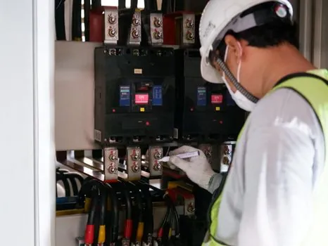
It is required when an operator must be inside or reaching into a hazard zone to start a dangerous motion, which is the same condition Ohio Administrative Code 4123:1-5-10 calls out for mechanical power presses: a two-hand trip protected against unintentional operation, with concurrent actuation, an anti-repeat feature, and a separate set of controls per operator on multiple-station presses [S1]. For a press brake guarding decision, OSHA inspectors generally look to 29 CFR 1910.212 plus ANSI B11.3, and a two-hand control is one of the listed point-of-operation safeguarding options alongside light curtains, pullbacks, and barrier guards [S4].
It is the wrong tool for routine energisation of a healthy machine from a control panel (a normal start-stop station is correct), for any application where the operator cannot physically reach the buttons (use a light curtain or area scanner instead), and for any task where tying or weighting the buttons would defeat the safety function (the anti-tie-down and anti-repeat requirements exist specifically to block this, and a hand-foot or single-button bypass is not a compliant substitute) [S1][S2][S3].
Installation, verification, and documentation discipline
Mount the buttons at the calculated safety distance D = K × T + C, with K = 63 in/s, T the measured total response time of the system, and C = 4 in for a bottom-reachable hazard or 6 in for an upper-reachable hazard; verify spacing at minimum 260 mm centre-to-centre to block single-hand actuation, and confirm supply pressure at 90 to 100 psi for pneumatic variants via a fail-safe pressure switch [S3]. Wire the contactor or downstream contactor pair so that a single contact welding cannot restart the motion without a fresh two-hand initiation, and verify the function at every shift change [S2][S3].
Document the risk assessment, the chosen Performance Level and Category, the measured response time, the calculated safety distance, the validation test on first install, and the periodic test interval; under OSHA 29 CFR 1910.217 enforcement, the absence of a written validation is one of the most common citation triggers, especially for electrical automation work cells that are repurposed after a control-system retrofit [S3][S4]. Operators training records and the inspection log for the two-hand station sit alongside the guarding method and the LOTO procedure in the same compliance file [S4].
Cross-references and standards to anchor the spec
For an electrical-work specification, anchor the part on five documents: ISO 13851 (Type III C, simultaneity window, spacing), ISO 13849-1 (Performance Level and Category), IEC 60204-1 (electrical equipment of machines, stop categories), EN ISO 12100 (risk assessment), and, for work tied to a press or other listed machine, OSHA 29 CFR 1910.217 plus the relevant ANSI B11 series (B11.3 for press brakes) [S1][S3][S4].
Trackable signals for the next quarter: any OSHA NEP update affecting 29 CFR 1910.217 enforcement at press-related facilities, and any revision activity on ISO 13851 or ISO 13849-1. Operators, EHS managers, and panel builders specifying LV electrical safety components should re-validate measured response time after any change to the downstream contactor, valve, or bus topology, since the safety-distance calculation is only as good as the T in it [S3][S4].
Related analysis: Manual Pallet Jack Specs for Retail Distribution: 2026 Selection Map.