
Water-ring vacuum pumps deployed in refinery cooling-water service are limited to 2000-4000 Pa ultimate vacuum on water working fluid, with isothermal gas compression that permits flammable or explosive gas handling when paired with explosion-proof motors [S3][S7].
Cooling-water loop certification for these units spans three failure-prone areas: rotor corrosion from high-sulphur feedstock (where 316L stainless trim is now standard for retrofit), seal and bearing temperature limits (bearing temperature rise not to exceed 35 °C, motor coil temperature not above 140 °C), and water-quality scaling managed like a low-pressure hot-water boiler per circulating-water hardness practice [S1][S3][S5].
Mechanical Pre-Start Checks Specific to Water-Ring Units
Foundation bolts, pump base bolts, motor bolts, and vacuum pump component fasteners must be confirmed torqued to spec before any cold turnover is attempted, and the turning gear must rotate evenly with the protective cover installed [S1]. Packing gland alignment is non-negotiable: skew introduces leak paths that defeat the seal water ring inside the pump chamber [S1].
The hand-check sequence also covers oil-cup grease volume, electrical insulation resistance, and a jogged forward/reverse test to verify rotation direction before coupling load [S1]. With a vacuum gauge on the suction flange and a working pressure gauge on the discharge, a DCS pre-start interlock typically requires inlet air valve CLOSED, gas-water-separator level above 50 mm, bearing temperature below 80 °C, and motor coil temperature below 140 °C [S1].
Motor coil temperature not higher than 140 °C and bearing temperature rise capped at 35 °C with absolute bearing temperature not higher than 80 °C are the operating thermal envelope stated by the OEM start/stop procedure [S1].
Cooling-Water Loop and Working-Fluid Conditioning
Plate-cooler industrial cooling water must be in standby before the water-ring pump is filled, with the working-water make-up line (demineralized water or condensate preferred) primed and the gas-water-separator overflow valve open [S1]. No liquid idling of the impeller is allowed: dry rotation damages the seal faces and the port plate within seconds [S1].
For stable suction vacuum, the working-water inlet temperature should remain below 30 °C, with 15 °C the most appropriate target; this is set by throttling the plate-cooler outlet valve until the return-water temperature matches design [S1]. A vacuum pump running hot sees the water vapour partial pressure rise and the achievable ultimate pressure deteriorate, so the cooler is a hard acceptance item, not a soft one [S1].
Circulating cooling-water hardness is the dominant scaling vector: managing vacuum-pump water quality against the same standard used for low-pressure hot-water boilers prevents both CaCO3 scale on the heat-exchange surface and galvanic corrosion of the cast-iron body [S5]. Open circulating systems with high return-water rates concentrate hardness ions across each pass, so a side-stream blowdown and chemical treatment program is part of the audit file [S5].
Materials and Retrofit Triggers for Corrosion Service
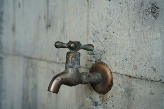
Refinery case histories show that switching the feedstock from slurry oil to waxy crude pushes high-sulphur salt and solid-impurity load into the roof-exhaust line, attacking the 300/600/1800 L/s roots rotors and accelerating wear as small particles open the rotor clearance [S3]. A common retrofit installs a 316L stainless water-ring pump at the inlet of each tertiary roots stage, run in parallel with the original 300 L/s roots unit and switched in based on service [S3].
316L stainless is selected because chloride- and sulphur-bearing condensate pitting attacks standard cast-iron trim; the L-grade (low carbon, ≤0.03% C) avoids sensitisation at the seal-welds during thermal cycling [S3]. Explosion-proof motors and compliant electrical gear extend the same water-ring stage into flammable-gas service, including chemical vacuum distillation, dehydration crystallisation, freeze-drying, and polyester-chip devolatilisation [S2].
Isothermal compression is the engineering reason water-ring stages can move condensable vapour without the oil-fouling seen on gas-ballast oil-sealed rotaries, which is why a roots + water-ring series keeps a low pumping rate at deep pressure while preserving the roots stage's high throughput near atmospheric [S2][S3].
Comparison: Water-Ring vs Roots + Water-Ring Unit vs Oil-Sealed Rotary
Selection comes down to four criteria: ultimate pressure, condensable-vapour tolerance, efficiency, and material compatibility with the cooling-water loop [S2][S3][S7].
On ultimate pressure, a single water-ring pump reaches 2000-4000 Pa on water working fluid and as low as 130 Pa on oil working fluid; a roots + water-ring series (typical industrial water-ring unit) reaches 1-600 Pa and can also operate as a low-pressure compressor at 1-2 × 10⁵ Pa gauge [S3][S7]. A standalone oil-sealed rotary can reach lower ultimate pressure but fails on condensable vapour load because the seal oil absorbs solvents and water, breaking the partial-pressure barrier [S2].
On efficiency, water-ring pumps are typically around 30%, with better designs up to 50%, well below dry-lobed roots units; the trade is paid back in isothermal compression and the ability to pull dust, water vapour, and reactive gases without metal-to-metal wear inside the chamber [S3].
On water-loop materials, water-ring units accept any cooling-water quality that the boiler-water standard allows, with 316L trim available for sulphur-bearing refinery streams; oil-sealed rotaries need seal-oil conditioning and gas-ballast to manage vapour, and roots units need inlet filtration to keep rotor clearances within tolerance [S3][S5].
Operating Limits and Common Audit Failure Modes
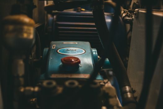
The most-cited commissioning failure is the running dry or partially primed water ring: the impeller-to-body clearance depends on a water film, and starting without it scores the port plate within one turnover [S1]. Audit checklists must therefore record working-water inlet valve open, gas-water-separator level above 50 mm, and overflow valve open before motor start is permitted [S1].
Second failure mode is the open cooling-water make-up bypass: the OEM procedure requires the manual bypass closed and the make-up solenoid valve controlled by level, otherwise the gas-water-separator floods and water carryover into the suction line collapses the vacuum [S1].
Third failure mode is thermal: a loop calibrator trace on the bearing RTD and motor winding PT100 should verify trip setpoints at 80 °C bearing and 140 °C winding during the SAT (site acceptance test), and the DCS interlock must enforce inlet-valve CLOSED + level > 50 mm + bearing < 80 °C + winding < 140 °C as a single AND-gated start-permissive [S1].
Documentation Required for an Audit-Ready File
Compile a per-unit dossier with: the OEM startup checklist signed off against the 10-item pre-start list (foundation bolts through drain-valve close-out), the DCS start-permissive logic diagram, the working-water and plate-cooler P&ID with material callouts, and the cooling-water chemistry log aligned to the low-pressure hot-water-boiler water-quality standard [S1][S5].
Add the explosive-atmosphere certificate when the pump is paired with an explosion-proof motor for flammable-gas service, and the 316L material certificate for any wetted trim in sulphur or chloride service [S2][S3]. For lab installations — where the same water-ring principle applies at smaller scale for filtration, rotary evaporation, and freeze-drying — the certification file collapses to a single OEM start/stop card plus a vacuum-gauge calibration record [S4]. A vacuum gauge calibration sticker on the suction flange dated within the last 12 months is the single most-checked artifact during a process-safety audit.
Two trackable signals for the next review cycle: the in-service date when the cooling-water hardness log first exceeds the 200 ppm CaCO3 threshold (side-stream blowdown should be commissioned by that point), and the bearing-vibration baseline at 90 kPa suction vacuum (interlock opens above this threshold per the OEM start sequence) [S1][S5]. For higher-pressure process integration, see the Immersion Cooling 2026 spec map, which covers dielectric-fluid cooling loops adjacent to the same kind of plate-cooler heat-rejection design used here. For ancillary MCC-side pneumatic control valves that share the cooling-water header, the Pneumatic Valve Actuator MCC RFQ spec map is a useful cross-reference on duty-cycle and instrument-air sizing.