
Specifying a valve positioner starts with three numbers the datasheet must give you cleanly: actuator stem thrust or torque, stroke in mm or degrees, and the input signal the host controller can actually deliver (4-20 mA, 0-10 V, HART, FOUNDATION Fieldbus, PROFIBUS-PA, or pneumatic 3-15 psi) [S2].
The global positioner market is forecast to reach USD 2.56 billion by 2030 at a 4.4% CAGR, with electro-pneumatic and digital positioners outgrowing legacy pneumatic units in upstream oil & gas and combined-cycle power duty [S4]. Selection mistakes — wrong diaphragm area, wrong Cv margin, ignored Joule-Thomson cooling — translate directly into inefficiency, oscillation, and recurring maintenance calls [S1].
Positioner Type Comparison: Pneumatic, Electro-Pneumatic, Digital
I/P (current-to-pressure) electro-pneumatic positioners accept a 4-20 mA signal and modulate a 3-15 psi or 6-30 psi pneumatic output to the actuator; digital smart valve positioner variants layer HART 7, FOUNDATION Fieldbus, or PROFIBUS-PA on top, adding autocalibration, partial-stroke testing, and EDD/DTM-based diagnostics [S2][S4]. MarketsandMarkets segments the market into pneumatic, electro-pneumatic, and digital positioners, with digital forecast to capture the majority of incremental revenue through 2030 [S4].
Use this trade-off frame on the bench before quoting: pneumatic only fits when plant air is already clean, dry, and 6-8 bar available and the host is purely analog; electro-pneumatic is the workhorse for retrofits on existing 4-20 mA loops; digital earns its premium on safety-instrumented duty where partial-stroke test coverage and asset-management hooks are specified.
Sizing Inputs: Cv, Actuator Thrust, and Valve Authority
Flow capacity is governed by the valve flow coefficient Cv (US) or Kv (metric, where Kv ≈ 0.865 × Cv), which is sized for the design flow at the worst-case inlet/outlet pressure differential and fluid temperature, not the normal-operating point [S1][S2]. The Cv calculator approach lets you back-solve for either flow or Cv given inlet pressure, outlet pressure, fluid properties, and temperature, and it works for both liquids and gases [S1].
Actuator selection follows: multiply the maximum required stem thrust (or rotary torque) by a 1.25-1.5 safety margin against the actuator's rated output at minimum supply pressure, then confirm the positioner's relay/nozzle capacity can keep up with the actuator's effective volume [S2]. Valve authority — the ratio of ΔP across the control valve to total loop ΔP — should sit between 0.3 and 0.5 for throttling duty; below 0.25 the loop becomes sluggish, above 0.75 you are wasting pump head and inviting cavitation on liquids [S2].
Service Fluid and Material Constraints
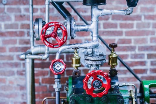
Material compatibility between the positioner's pneumatic tubing, relay housing, I/P transducer elastomers, and the process media is non-negotiable on sour, acidic, or oxygen-enriched service — NACE MR0175 / ISO 15156 limits the hardness and composition of wetted metals in H₂S-bearing hydrocarbons, and oxygen-cleaning per cleaned-for-O₂ spec adds its own elastomer constraints [S1].
Temperature derating is the silent killer: pneumatic supply air that drops 1.7°C per 100 psig expansion (the Joule-Thomson effect) can frost a positioner relay in winter or on high-pressure gas drop applications, and a -40°C to +85°C electronics window is the typical industrial band on modern digital positioners, with ATEX/IECEx variants on the upper end sized for Zone 1 hazardous-area mounting [S1][S3].
Fail-Safe Mode and Actuator Action
Every positioner has a paired actuator action: spring-return single-acting fails closed (FC) or open (FO) on air loss, double-acting stays put on air loss (fail-last, FL) and uses the positioner plus a solenoid or lock-valve to drive a deliberate safe state [S2]. Choosing FC vs FO is a process-safety call — a fuel-gas block valve at a burner typically fails closed; a cooling-water valve on a reactor jacket typically fails open; a turbine-driven compressor anti-surge valve typically fails open to protect the wheel [S2].
Signal-side failure must be specified separately: a positioner that loses its 4-20 mA command can be configured to drive fully to one end, hold last position, or follow a user-set curve, and on a HART or FOUNDATION Fieldbus segment the same logic lives in the device's function-block configuration rather than in the I/P converter [S2][S4].
Who Should NOT Pick the Mainstream Electro-Pneumatic Option
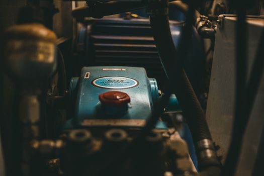
Skip a standard 4-20 mA I/P positioner on subsea Christmas trees, where all-electric or hydraulic-actuated smart positioners with redundant communication dominate; on high-cycle modulating duty above roughly 200 cycles per minute where piezo or stepper-driven positioners outlast pneumatic relays; and on sanitary or hygienic lines where a flush-mount stainless housing, IP66/67, and EHEDG cleanability are written into the URS [S3].
For a related dive into the broader control-valve sizing math including Cv for ball valve and globe bodies, the engineering toolbox Cv/Kv and valve-authority resources are the standard first stop, and for sizing the upstream actuation hardware itself the hydraulic actuator sourcing map lays out thrust bands and lead-time by region.
Installation, Calibration, and Commissioning Checks
Commissioning a digital positioner is a five-step loop: stroke the actuator electrically to fully closed and confirm the low reference on the position sensor, stroke to fully open and confirm the high reference, set the 4-20 mA input mapping, set the tight shut-off and signature thresholds, and finally run the auto-tune routine that the device uses to characterise its PID gains against the specific actuator's effective volume and friction profile [S2][S3].
Partial-stroke test (PST) and full-stroke travel logs are now standard deliverables from HART 7 and FOUNDATION Fieldbus positioners, feeding directly into IEC 61511 safety-instrumented-function proof-test intervals and reducing the manual proof-test burden on shutdown valves by an order of magnitude in the right architecture [S2][S4]. For buyers cross-checking compatible sensors and signal conditioning upstream of the positioner, the multi-gas detector spec map follows the same HART-mapped, 4-20 mA-plus-digital logic and is a useful reference for signal-trunk design.
Shortlist Logic and Trackable Signals
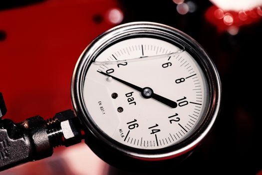
Final pass before release: confirm Cv sized for worst-case ΔP at 1.25× design flow, confirm actuator bench pressure at the positioner relay output exceeds 1.25× the maximum required stem thrust, confirm hazardous-area certification (ATEX 2014/34/EU or IECEx) matches the Zone/Class, and confirm the digital protocol (HART 7, FF, PROFIBUS-PA) is in the host controller's DD/CF library [S1][S2][S4].
Two trackable signals to watch into late 2026: FOUNDATION Fieldbus and PROFINET-PA adoption curves in brownfield power and water utilities, and the next NAMUR NE 107 diagnostic-category compliance push from the major DCS vendors — both will reshape the digital positioner spec shortlist and feed back into actuator sizing assumptions on the next project. For process plants that pair a positioner with a precision regulation element, the balancing valve encyclopedia entry covers the matching Cv/rangeability math on the HVAC and hydronic side of the same loop.