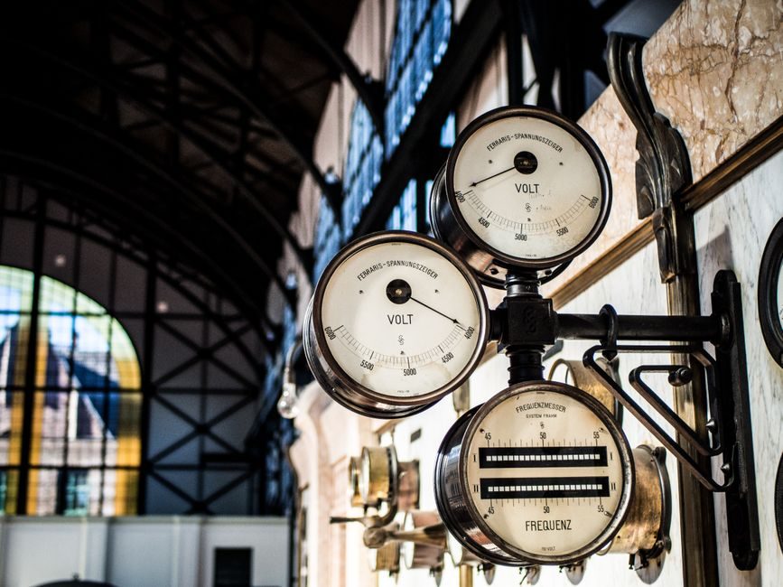
Vibration sensors for industrial duty split into four transducer families — piezoelectric accelerometers, electromechanical velocity pickups, eddy-current proximity probes, and micro-electromechanical (MEMS) chips — each defined by a different physical variable and a different usable frequency band [S1].
A working selection is therefore driven by three decisions before any brand comparison: which shaft or casing parameter the sensor must measure (vibration displacement, velocity RMS, or acceleration g), which frequency range the host machine generates, and whether the output is an analog 4-20 mA loop, a charge / IEPE signal, or a digital bus [S1][S2].
Four Sensor Families and What Each Measures
Industrial vibration sensors are defined by the physical quantity they transduce, not by their packaging. An accelerometer outputs an acceleration proportional to g, with a flat response from roughly 0.5 Hz to over 10 kHz in general-purpose industrial units, and it is the default transducer on most modern condition-monitoring retrofits [S1]. A velocity pickup integrates acceleration internally and reports mm/s RMS, matching the ISO 10816-3 family of severity charts for medium-power rotating equipment at 10-1,000 Hz [S1]. An eddy-current (proximity) probe measures non-contact shaft displacement in micrometres or mils at 0-1 kHz and is the only family that can be mounted in an API 670-compatible radial or axial position [S1]. A MEMS device is a silicon die etched into a proof mass; the omni-directional VBS06 device from a Taiwan OEM targets consumer and security applications such as wake-up signalling on remote controllers, GPS start systems, alarm panels, anti-theft modules, and bicycle-lamp flashers, where cost and battery life dominate over metrology [S2].
Selection rule used on the shop floor: pick the transducer family first, then the mounting and connector. Accelerometers cover roughly 80 % of modern retrofit work, velocity pickups persist on legacy frames and 50 Hz / 60 Hz mains-driven equipment, and proximity probes are reserved for sleeve-bearing turbomachinery where shaft-relative displacement is the only meaningful health indicator [S1].
Specifications That Drive the Shortlist
Three numbers decide the bill of materials more than any other: frequency response (±10 % band), sensitivity (mV/g or pC/g for charge-mode accelerometers), and the operating temperature window, which typically spans -55 °C to +121 °C for epoxy-sealed industrial units and reaches +482 °C with mineral-insulated cable and welded construction [S1]. The second tier of specs is mechanical: case material (304 / 316 stainless for wash-down or chemical exposure, titanium for high-temperature and aerospace), connector pattern (top-exit M5 / M7 / 10-32, side-exit MIL-C-5015, or integral cable), and mounting (stud, adhesive, magnetic, or hand-held probe) [S1].
On the electrical side, the buyer must commit to one of three signal paths before quoting. Charge-mode accelerometers output a high-impedance piezoelectric signal that needs a charge amplifier or an in-line IEPE conditioner; IEPE units integrate a JFET source follower and run on a 2-10 mA constant-current loop, which simplifies the cable plant dramatically; and 4-20 mA loop-powered vibration transmitters output a process-current value that drops straight into a DCS or PLC analog input, ideal for hazardous-area retrofits where only two conductors are safe to run [S1].
Hazardous-Area, Output Protocol, and Cabling
For Zone 1 / Class I Div 1 duty, intrinsically safe (IS) vibration transmitters loop-power a certified accelerometer, monitor the loop at a galvanic barrier in the safe area, and present a 4-20 mA signal that the DCS already understands. Explosion-proof or increased-safety enclosures (ATEX category 2 / IECEx Gb) are used for higher-power installations where IS energy budgets are impractical. Cabling matters: charge-mode runs should stay under about 6 m and use low-noise cable; IEPE tolerates 30-100 m on twisted pair; 4-20 mA loops are routinely pulled hundreds of metres with shielded twisted pair and a clean earth at the barrier end. [S3]
Where condition-monitoring is the goal rather than trip protection, raw IEPE or charge outputs feed a dedicated vibration analyzer or a multi-channel vibration meter that resolves FFT spectra, waveform time capture, and demodulated envelope spectra for bearing-fault detection. Trend storage is the deliverable — weekly velocity RMS for unbalance, monthly g-RMS plus enveloping for bearings, and proximity-probe DC gap plus 1× vibration amplitude for sleeve-bearing machines.
Comparison of the Four Main Transducer Types
A direct comparison lines the four families against four buyer-critical criteria. (1) Frequency band: accelerometer 0.5 Hz to 10+ kHz; velocity pickup 10 Hz to 1 kHz; proximity probe DC to 1 kHz (shaft-relative only); MEMS consumer 0-500 Hz typical. (2) Typical mounting: stud / adhesive / magnetic; handheld wand or stud; bracket-mounted in API 670 box; PCB or flexible lead. (3) Output: charge, IEPE, or 4-20 mA; mV / mm/s RMS; V / µm shaft gap; digital interrupt or analog. (4) Best-fit duty: general-purpose machine health; ISO 10816-3 trending on legacy frames; sleeve-bearing turbomachinery; security, anti-tamper, and IoT wake-up [S1][S2]. The rule of thumb: use accelerometers for new condition-monitoring, velocity pickups for retrofit on legacy frames, proximity probes for sleeve-bearing rototech, and MEMS only when cost-per-node and battery life beat spectral resolution.
Who Should NOT Use a MEMS or a Velocity Pickup
MEMS devices such as the omni-directional VBS06 are explicitly designed for security, alarm, GPS-start, anti-theft, and bicycle-lamp / sporting-shoe flashing, with a no-electricity, wake-up-by-shock feature set aimed at power-saving applications — not at industrial predictive maintenance [S2]. Specifying that family for a motor-health FFT deliverable will fail on dynamic range (consumer MEMS rarely exceeds 60-70 dB), bandwidth (typically sub-500 Hz), and survivability under industrial shock and temperature. Conversely, a velocity pickup is the wrong choice for a high-speed gearbox above about 5 kHz gear-mesh frequency, for a precision linear guide or crossed-roller guide health-monitoring system, or for any machine where the ISO 10816-3 velocity charts do not apply.
Acceleration g-measurement is the only credible metric above 1 kHz, which is why every modern API 618 / API 617 frame and most precision-spindle applications have migrated to IEPE or charge-mode accelerometers despite the higher cost-per-channel [S1].
Mounting, Cabling, and Field Failure Modes
Mounting is the most common cause of bad data. A stud-mounted accelerometer with a torque-controlled 2-4 N·m fastener and a prepared, flat, bright surface can extend the usable bandwidth to the kHz range, while an adhesive pad or magnetic base typically loses one or more octaves at the high end and is unfit for permanent ISO 10816 trending. Cable-induced noise on charge-mode circuits shows up as low-frequency drift and is the number-one reason "the accelerometer is bad" tickets are opened; switching to IEPE eliminates the failure mode at the cost of needing a constant-current source at each channel. [S2]
On the inspection side, two field-failure modes dominate. Second, moisture ingress at the connector or the conduit seal: insulation resistance drops below 10 MΩ, charge-mode bias drifts, and a low-frequency wander appears. The fix is the same in both cases — replace the cable and the sealing grommet, then re-verify against a handheld shaker with a known 100 mV/g @ 100 Hz reference.
Procurement Shortlist Logic for 2026
Define the application first: which machine class (ISO 10816-3 severity band, API 670 radial-vs-axial, or API 618 reciprocating-compressor frame), which alarm philosophy (trip-only or trip-plus-trend), and which hazardous area (safe area, Zone 2, Zone 1). That defines the transducer family. Then set the non-negotiables: sensitivity (≥ 100 mV/g for general monitoring, ≥ 500 mV/g for low-frequency large-casing work), temperature rating (-55 °C to +121 °C is the industrial default), and the supply / output pair (IEPE + 4-20 mA loop transmitter is the most retrofit-friendly). Reject anything that misses two of the three; everything else is a lead-time call. [S2]
Lead-time risk for industrial piezoelectric crystals has eased in 2026 versus the 2022-2023 peak, but expect 8-14 week factory lead times on 1-2 lot orders for general-purpose IEPE units and longer for custom hazardous-area loop-powered transmitters.
For related coverage, see Modified Bitumen Membrane Installation: 2026 Spec-Driven Field Guide.