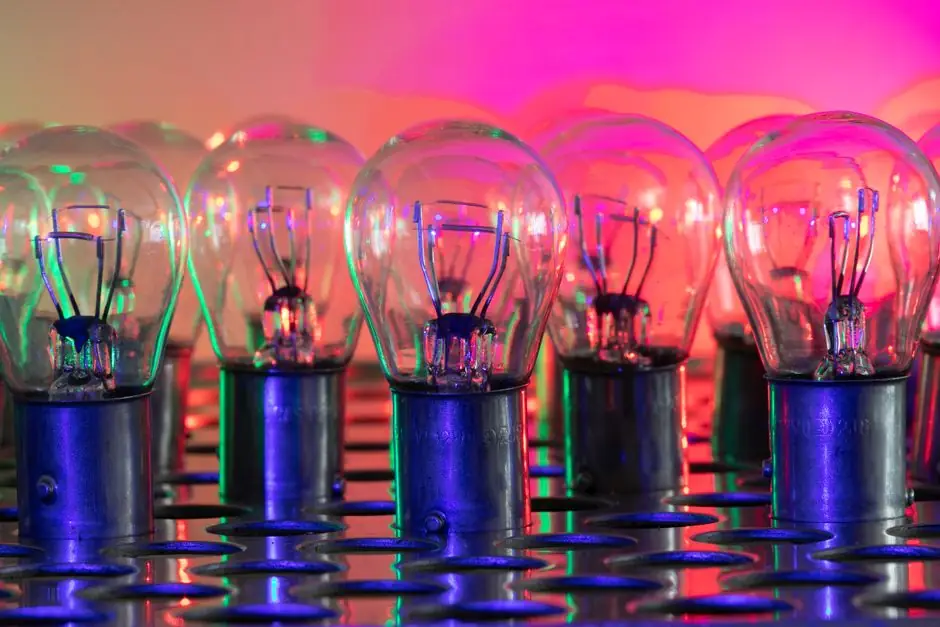
The dominant choice in industrial machine vision is the LED light source, specified by wavelength, geometry, and current-mode drive, with overdriven pulsed operation reaching up to 10x the continuous rating when paired with a matched lighting controller [S1][S7].
Selection starts with the inspection feature, not the camera: surface texture, edge definition, color contrast, or silhouette, and ends with a current-regulated driver, because LED brightness tracks junction current far more tightly than supply voltage [S1][S2].
Why lighting geometry decides the inspection result
Lighting geometry is the first decision branch, and Keyence's selection guide orders the options by the feature shape: specular reflection, diffuse reflection, or backlighting as the three primary methods, each isolating a different optical response from the target [S3].
Basler's taxonomy lines up the same families by optical function: headlight (front diffuse) for matte surfaces, transmitted (back) light for outline and dimensional measurement, and dark field for shallow-angle reflection that turns scratches and engravings into high-contrast bright features on an otherwise dark image [S2]. Quality Magazine's 2019-09-01 reference list expands this to five common techniques: ring, back, bright-field / dark-field directional, low-angle ring, and on-axis, with the choice driven by target reflectivity, translucence, and standoff distance [S5].
Comparing the five core lighting geometries
Ring lights mount coaxially around the lens and give the most uniform, near-shadow-free illumination of general-purpose parts, which is why they remain the default in assembly monitoring and optical inspection; bar lights project from an elongated emitter and can be aligned at any angle, so they double as dark-field sources and as multi-side arrays on long workpieces [S2].
Back lighting places the part between emitter and sensor to silhouette holes, bubbles, and outer dimensions at the cost of all surface texture, while horizontal / low-angle ring variants push light from the side to make edges and scratches pop, and that side-fire geometry is the standard pattern for transparent parts like windows and films [S2][S5]. A criteria-based comparison on four decision axes, geometry versus recommended feature versus strength versus main failure mode, follows: ring light scores best on general uniformity but flattens surface defects; bar light wins on long workpieces and configurable dark-field angles but needs careful mechanical alignment; back light is unbeatable for outline and dimensional metrology but loses all surface data; low-angle / dark-field is the only geometry that exposes fine scratches on glossy surfaces at the cost of strong shadow sensitivity.
Wavelength and color: matching the LED to the part and sensor
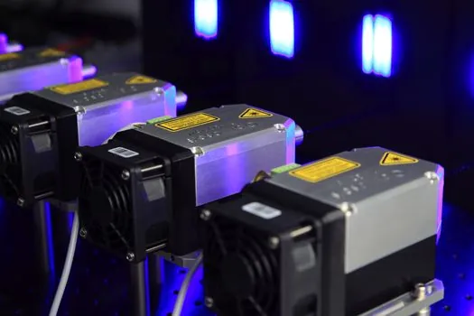
Wavelength is selected after geometry, and Basler's 2023-05-09 guidance is explicit: use red illumination on a monochrome camera when you need maximum contrast on a wide range of objects, because monochrome sensors have higher responsivity in the red band than in blue or green and that sensitivity gap directly improves signal-to-noise [S2].
Common industrial LED wavelengths span roughly 470 nm blue through 940 nm near-infrared, with green around 525 nm and red around 625 nm dominating the visible band; near-IR is the workhorse for silicon-wafer and PCB inspection because silicon and many coatings are partially transparent above ~700 nm, letting subsurface features show through. A monochrome sensor should pair with the longest wavelength the feature still absorbs, while a color sensor typically needs white or broadband illumination to preserve hue information; pairing a 940 nm IR LED with a color Bayer sensor is a common mis-spec, because the Bayer IR-cut filter attenuates that band before it reaches the photodiodes.
Brightness, stability, and why current control beats voltage control
LEDs are current-driven devices, so a small change in forward voltage produces a disproportionately large change in optical output, and this is non-negotiable at production-line accuracy: a 10% change in incident light level can shift a simple vision calliper measurement by roughly 0.5% [S1].
Pulsing the LED only during camera exposure cuts thermal drift and enables overdrive: with a matched lighting controller, LEDs can be safely pulsed at up to 10x the published continuous rating, which is the standard way to freeze motion on high-speed lines or to out-battle ambient light interference on an established station [S1]. Vico Imaging's overview and Gardasoft's white paper both treat brightness as one of the primary spec axes, but the operational rule is to specify the continuous rating, the safe pulse current, the maximum pulse width, and the maximum duty cycle as four separate numbers, not as a single wattage.
Five-factor sourcing check before you order a sample
Quality Magazine's 2019-09-01 checklist condenses the buying decision into five factors: spectral content, lighting geometry, intensity stability, lifetime / MTBF, and controller integration, and the relative weight of each depends on whether the line stops when the light fails or whether the application can tolerate a brief image-quality drift [S5].
For industrial procurement the practical shortlist is: (1) wavelength band, with the part / sensor pairing spelled out; (2) geometry, with the standoff distance and field of view dimensions written next to it; (3) continuous and pulsed current rating, sourced from the LED data sheet and not from the lamp housing; (4) controller interface, including trigger latency, opto-isolated inputs, and Ethernet / web diagnostics for live current and voltage readback; and (5) thermal and IP rating matched to the cabinet environment. See a related process-side walkthrough of Industrial Barcode Scanner Sizing: A Spec-Driven Selection Walkthrough for a similar controller-driven criteria flow, and the Gas Chromatograph Suppliers: 2026 Maker Map, Process vs Lab Lines, and Sourcing Specs piece for the same kind of vendor / process split that applies to specialty light suppliers.
Where LED is the wrong call
LEDs are not universal. Fluorescent tubes are still preferred for very large, diffuse area illumination where the lower cost per square centimeter and the wider spectral band offset the strobing and lifetime limits of LED panels; quartz halogen retains a niche where a broad, continuous spectrum from roughly 320 nm to 2500 nm is mandatory, such as some color-critical print inspection [S7].
For a high-speed line where the camera exposure is in the single-digit microsecond range, a xenon strobe can out-pulse a comparable LED on raw peak radiance, but at the cost of an arc-lamp power supply, a finite tube life in the order of 10^8 to 10^9 flashes, and a broader spectrum that the bandpass filter must cut down. In all three cases the deciding metric is peak spectral radiance at the working wavelength divided by total cost of ownership over the planned station life, and that arithmetic almost always lands on a current-controlled LED for any new build in 2026.
Trackable signals: watch for vendor datasheets that publish continuous current, safe pulse current, maximum pulse width, and maximum duty cycle as four separate values rather than as a single wattage, and treat that as the proxy for a serious industrial LED; for machine vision system integrators, that datasheet discipline is the most reliable indicator that the supplier's vision controller and vision imaging chain will hold its calibration over the full production shift.