
A vortex flowmeter on a compressed air header is governed by four independent evidence packages: pressure equipment compliance (PED 2014/68/EU or its national equivalents), explosion protection for the area classification (ATEX 2014/34/EU or IECEx), metrology/calibration traceability, and process-mechanical fitness verified against the Strouhal-based turndown claimed by the vendor [S1][S3].
For air service specifically, the process fluid is non-conductive, clean, and single-phase, which is the design sweet spot for vortex shedding: the bluff body sheds a stable Kármán vortex street and the shedding frequency scales linearly with velocity, giving a turndown of roughly 10:1 to 20:1 on most reduced-bore and full-bore bodies [S3][S6].
Process scope and meter selection on a compressed air header
Vortex shedding is a bluff-body phenomenon governed by the Strouhal number St = f·d/v, where f is shedding frequency, d the bluff body width, and v the flow velocity; von Kármán established that a cylindrical bluff body produces a vortex street with a transverse-to-longitudinal spacing ratio of 0.281, and modern delta-shaped bodies are designed to keep St constant across the measuring range to preserve linearity [S3].
For compressed air headers, the operating Reynolds window is the gating decision: Yokogawa rates its digitalYEWFLO at ±1.0% of reading for gas and steam down to a velocity-limited lower bound, with the Reduced Bore variant using an integral concentric reducer and expander to extend stability into the low-flow end where the bluff body would otherwise produce signal starvation [S1][S6]. Endress+Hauser likewise notes that delta-shaped bluff bodies deliver a particularly high linearity and accuracy across the measurement range [S3]. The practical implication on an 80-psig plant air header is that the engineer must size to the minimum daytime flow, not just the average, because the meter will lose accuracy if the operating point drops below the published Reynolds or velocity threshold.
Pressure equipment and material compliance evidence
Because compressed air headers are pressurised, the meter body, flanges, and pressure-containing welds fall under the Pressure Equipment Directive 2014/68/EU in the EU and ASME B31.3 in the United States, so the supplier must furnish a PED Conformity Assessment (Module B + D, or B + F typical for Category III) and a nameplate showing the fluid group, design pressure, and test pressure [S10].
Stainless steel wetted parts (typically 316L) are the default for clean, dry compressed air; carbon-steel bodies with stainless trim are common on larger line sizes above DN150 for cost reasons, but moisture-laden air upstream of aftercoolers will pit carbon steel and bias the long-term calibration, so material traceability certificates to EN 10204 3.1 are part of the same documentation pack [S6][S7]. NACE MR0175 compliance is not normally required for air service, but it should be specified if the same header will see sour-gas depressurisation events or intermittent hydrocarbon contamination.
Area classification and explosion protection
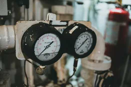
Compressed air by itself is not flammable, but most plant air headers run through Zone 2 (or Class I, Div 2) spaces because the rack also carries hydrocarbon-bearing lines, and a vortex meter with an integral transmitter typically carries a non-incendive or Ex ec marking that has to be on the same certificate family as the rest of the instrumentation on the header [S2].
The user must demand the ATEX EU-Type Examination certificate (for ATEX 2014/34/EU) or the IECEx Certificate of Conformity (CoC) and Equipment Approval Schedule, and verify that the marking string (e.g. Ex ec IIC T6 Gc, IP66/67) covers both the gas group and the surface temperature class actually present at the header location, since a T4 vs T6 difference can determine whether the meter can sit beneath insulation or adjacent to a steam line. A related primer on the standard families is in the safety certification reference, which covers the audit evidence pattern these marks require.
Metrology, calibration, and Strouhal-based accuracy
Flow calibration for compressed air is most commonly performed on a bellmouth or nozzle test rig traceable to NIST, NIM, or NPL, and the certificate must report the measured error as a function of flow rate, not a single ±X% number, because vortex accuracy degrades at both ends of the turndown range [S1][S3].
Yokogawa publishes its digitalYEWFLO accuracy as ±1.0% of reading for gas and steam within a stated Reynolds window, with the Reduced Bore Multi-Variable (DY/MV) option reaching ±0.75% of reading in the optimal D×1000 ≤ Re range [S6]. Endress+Hauser emphasises that linearity is the property the bluff-body geometry is engineered to preserve, because once St drifts from constant, the volume flow derived from vortex count becomes biased [S3]. The calibration certificate should therefore be cross-checked against the same Re range declared on the nameplate, otherwise the warranty accuracy is void for low-load operation. For a useful primer on the underlying device class, the vortex flowmeter entry summarises the principle, the bluff-body variants, and the typical turndown behaviour.
Inlet straight-run, vibration, and installation verification
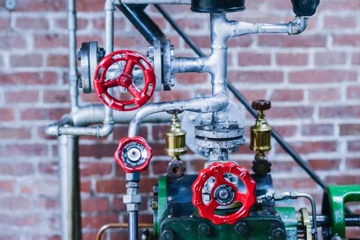
ISO 5167 and most vortex manufacturers require 10D upstream and 5D downstream of straight pipe, with the upstream length extended to 20-30D after a single elbow or a control valve, because distortion in the velocity profile shifts the effective bluff-body Strouhal constant and biases the reading [S3].
Plant air headers are notoriously vibration-rich because reciprocating compressors and the receiver tank couple pulsations directly into the run, and the vendor's adaptive noise suppression (ANS) and spectral signal processing (SSP) features, like those on Yokogawa's digitalYEWFLO, exist specifically to reject this pipe-borne vibration so the meter can be installed without mechanical dampeners [S1]. The acceptance test for vibration rejection is a simple two-step: log the un-installed header vibration in mm/s RMS, install the meter, and verify that the analog output (4-20 mA or HART) does not develop a sinusoidal ripple correlated with the compressor crank frequency. If it does, the audit evidence should record the addition of a flexible coupling or a support bracket change rather than a re-calibration.
Output protocols, diagnostics, and lifecycle documentation
Modern vortex meters for compressed air ship with HART 7 over a 4-20 mA loop, optionally Foundation Fieldbus or PROFIBUS PA, and the user should confirm the host system supports the same protocol revision before specifying, since mismatched revisions cause DD file load failures at commissioning [S1][S2].
Self-diagnostics are now part of the audit pack: a de-clogging alarm, sensor-health flags, and verification tools like the FSA130 generate a printed evidence file that satisfies internal IMEA and external ISO 9001 calibration-confidence reviews without breaking the process [S1]. The verification certificate is time-stamped and stored in the device DTM, which is also where the next-due calibration date is logged, and most plants now require this evidence to feed the CMMS rather than a paper-only binder. For context on adjacent inline measurement choices used in the same utility room, see ultrasonic flowmeter liner compatibility.
Common failure modes and what to demand from the vendor

The four audit failures we see repeatedly on compressed air headers are: (1) PED category not on the nameplate, only in the brochure, (2) ATEX/IECEx mark missing the surface temperature class, (3) calibration certificate outside the as-installed Reynolds window, and (4) inlet straight-run shorter than the ISO 5167 minimum because the location was forced by pipe routing [S3][S10].
To prevent each, require: a nameplate photo with the certificate numbers in the FAT report, the Ex string in the purchase order, a calibration table plotted against the actual operating Qmin and Qmax, and a marked-up isometric showing the straight-run dimensions before mechanical installation begins. The supplier should also be asked for a two-year vibration-validated accuracy statement, because air service is benign chemically but punishing mechanically, and a vendor that has published long-term drift data is one that has actually run the meter on a compressor header rather than a steam line.
Verify the supplier's certificate is real by checking the notified-body number on the EU Commission NANDO database for ATEX, the IECEx OD database for IECEx, and the issuing laboratory's accreditation scope for the calibration. A practical next step is to issue a vendor audit questionnaire covering the four evidence packages above and a factory acceptance test that witnesses a live 4-point calibration on actual shop air, since the cheapest audit pass is one performed before the meter is shipped.
Component reference pages worth checking: air pick.