
Industrial warning sign installation is governed by substrate selection, retroreflective sheeting class, mounting height, and torque-controlled post anchorage, with ANSI Z535.2 setting the hazard-alert sign format and ISO 7010 standardising the W-series pictograms (yellow triangle, black border) used across the EU, UK, and most of Asia [S1][S2].
Specifying engineers typically treat the sign as a four-component assembly — substrate (aluminium, composite, fibreglass), sheeting (engineer grade, high-intensity prismatic, diamond grade), post (galvanised steel, breakaway), and anchorage (concrete footing, bolt-on) — and acceptance hinges on each interface, not the panel face alone.
Substrate Selection: Aluminium vs Composite vs Fibreglass
0.063 in (1.6 mm) aluminium 5052-H38 remains the default outdoor substrate because it tolerates -40 °C to +90 °C and resists UV chalking longer than 0.080 in ABS or polycarbonate panels [S1].
Composite panels (e.g. 3 mm aluminium-polyethylene-aluminium sandwich) weigh roughly 40% less than solid aluminium of equal stiffness, which matters when crews install 4 ft × 4 ft panels at 12 ft mounting height using a single-person lift; fibreglass-reinforced plastic (FRP) is reserved for chemical-exposure zones where pH falls below 3 or above 11, conditions that pit aluminium within 18–24 months. For corrosion audits, the linear guide reference helps frame the same substrate-decision logic applied to motion hardware.
Do not route signs through the same QA chain as crossed roller guide components — sign substrate acceptance is visual plus thickness gauge, not CMM, but the documentation discipline is identical.
Retroreflective Sheeting: ASTM D4956 Type IV vs IX vs XI
ASTM D4956 Type IV (high-intensity prismatic) returns a minimum 250 cd/lx/m² at 0.2° observation, -4° entrance, while Type IX (diamond grade VIP) returns 750 cd/lx/m² under the same geometry — the jump matters on unlit rural roads where headlamp illumination drops below 5 lux at 150 m [S2].
Type XI (diamond grade DG3) extends the long-range performance to 1000 cd/lx/m² and is the only class that maintains ASTM D4956-22a photometric tables beyond 5 years of Florida or Arizona UV exposure. Specifying Type IV on a Class A roadway under MUTCD guidance is the single most common retroreflectivity audit failure. Sign-face compliance maps to warning sign pictogram geometry — ISO 7010 W-series symbols must retain ≥ 50% of original luminance at the 7-year replacement interval, otherwise MUTCD §2A.08 retroreflectivity thresholds are violated.
Mounting Height, Offset, and Hazard-Zone Mapping

MUTCD §2A.18 sets the minimum mounting height at 7 ft (2.13 m) to the bottom of the sign in urban pedestrian zones and 5 ft (1.52 m) in rural rural-area postings where the path is not used by pedestrians — rural posting allows lower height because the hazard envelope is vehicle-only [S1].
Lateral offset from the travelled way is 2 ft minimum, 6 ft typical, and 12 ft preferred on freeways; crossing into the clear zone (per AASHTO Roadside Design Guide) without a breakaway post triggers roadside hardware non-compliance. Hazard-zone mapping follows ANSI Z535.3 with three concentric radii — the alert zone (proximity awareness), the command zone (mandatory action), and the danger zone (PPE-required) — each tied to a different pictogram class from the warning sign W-series.
Compare the layout against the skylight installation guide logic: flashing and sealing acceptance maps 1:1 to the torque and lap-seal acceptance that a sign post requires at the concrete interface.
Post Anchorage: Footing Depth, Concrete Class, and Torque
A 2 in × 2 in × 8 ft (51 mm × 51 mm × 2.44 m) galvanised steel post in soil class A-1 requires a 30 in (762 mm) deep footing with 6 in (152 mm) diameter sonotube and 3000 psi (20.7 MPa) concrete, per AASHTO LTS-6 breakaway-stub guidance [S1][S2].
Breakaway slip-base couplings must be torqued to 40–50 ft-lb (54–68 N·m); under-torque causes the post to lean under 30 mph wind loading, over-torque defeats the breakaway function and creates a fixed-object hazard. Bolt-on installations to existing I-beam or H-beam structures use 5/8 in (16 mm) A325 hot-dip galvanised bolts torqued to 150 ft-lb (203 N·m) with a lock washer and an isolating nylon washer to prevent galvanic corrosion at the dissimilar-metal joint.
Failure Modes: Lean, Fade, Peel, and Torque Loss
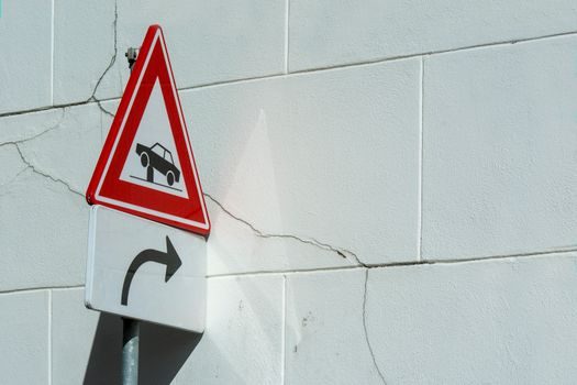
Field failure mode #1 is post lean caused by frost-heave in clay soils — the fix is a 4 in (102 mm) gravel drainage layer at the footing base, not a deeper hole, because frost depth in the worst US climate zone is 48 in but the failure is water-driven.
Field failure mode #2 is retroreflective fade before 7 years, which traces to Type IV sheeting specified on a sun-loaded south-facing panel; replace with Type IX and the service life doubles. Field failure mode #3 is sign-face delamination caused by incompatible adhesive systems — overlay on old Type III with Type IX requires heat-lamp removal of the legacy panel, otherwise trapped-solvent bubbles form within 6 months. Field failure mode #4 is anchor-bolt torque loss from vibration; re-torque to spec at 12-month intervals on any post within 50 ft of a rail line or vibrating equipment.
Acceptance Test Sequence and Documentation
Acceptance step 1 is substrate thickness gauge at four corners — reject if any reading is below 0.060 in for 0.063 in nominal aluminium.
Acceptance step 2 is retroreflectometer reading at 0.2°/-4° geometry with a calibrated handheld unit (RoadVista 922 or equivalent) — must meet the ASTM D4956 type-class minimum at the as-installed orientation. Acceptance step 3 is plumb verification: ≤ 1° from vertical in both axes using a digital level. Acceptance step 4 is torque audit on every breakaway coupling, recorded on the as-built sheet alongside the crossed roller guide-style serialised part list. Acceptance step 5 is photographic record of the pictogram orientation relative to the approaching traffic flow, filed against the asset ID for MUTCD §2A.08 retroreflectivity re-inspection at the 7-year mark.
Cross-reference layout of substrate/sheeting/post maps to the same decision structure used in skylight installation guide flashing-class selection — both jobs reward engineers who lock the spec before the pour and reject on the gauge, not the eye.