
An aircraft stretcher installation must be designed for a 170 lb (77 kg) occupant against the FAR 25 flight, ground, and emergency-landing inertia forces cited in Transport Canada ACSI 32 (Issue 1, 1983-04-15) [S3], and its supporting structure must allow rapid detachment for crash evacuation per FAR 25.803 [S3].
The same word "stretcher" covers two engineering worlds: the fixed aeromedical kit (Aviation Fabricators AF-510, FAA STC SA52RM, Cessna 500/550/S550/560 series) [S2] and the wheeled EMS cot (Stryker Power-PRO 6506, Performance-PRO 6086) [S4][S5]. They share the load-passenger-and-restrain logic but diverge on certification basis, attachment hardware, and the inspection regime that follows.
Regulatory Frame: FAR 25 and ACSI 32 Stretcher Load Case
Transport Canada ACSI 32 was issued 1983-04-15 to formalize stretcher installation guidelines for Transport Category aircraft, drawing directly from FAR 25 [S3]. The framework states that a person using the stretcher must not suffer serious injury in an emergency landing under the inertia forces specified in FAR 25.785(a), and that the installation is designed for a 170 lb occupant across all relevant flight, ground, and emergency-landing conditions per FAR 25.785(i) [S3].
Structural substantiation is permitted two ways: (1) treat the critical forward, sideward, downward, and rearward loads as acting separately, or (2) use selected load combinations provided the required strength in each specified direction is substantiated, per FAR 25.785(i)(l) [S3]. Each projecting object that could injure the occupant or moving crew must be padded per FAR 25.785(e), and the location must not obscure required exit, seat-belt, or no-smoking signage, nor obstruct any emergency-exit access route per FAR 25.813(a) [S3]. For an industrial reference on adjacent load-frame work, see this selection map for slewing ring bearing types.
Aircraft Stretcher Kit: AF-510 Hardware and Seat-Track Anchor Pattern
Aviation Fabricators Document AF-510, Revision IR (2013-10-17), is the Instructions for Continued Airworthiness for the stretcher kit installed under FAA STC SA52RM on Cessna 500, 550, S550, and 560 series aircraft, and the document explicitly states it complies with 14 CFR 25.1529 [S2]. The kit is a self-contained assembly that mounts to the existing cabin seat track, which is what differentiates a certified aeromedical retrofit from a one-off floor bracket [S2].
Per ACSI 32, the stretcher restraint must prevent unwanted movement during turbulence or emergency landing (FAR 25.785(c)) and the attachments must allow rapid detachment for evacuation in crash landings (FAR 25.803) [S3]. In practice that means the seat-track latches are the primary structural interface, the pad-and-cushion assembly is the patient interface, and the restraint straps cross the body to spread the inertia load the same way a lap-belt does on a standard passenger seat. For an analogy on adjacent track-style industrial hardware, the linear guide selection logic uses a similar profile-rail anchor pattern with rapid-release features, though the load class is different.
ICA Tasks and Inspection Intervals Under 14 CFR 25.1529
AF-510 Revision IR satisfies the 14 CFR Part 25 Appendix H, paragraph H25.1(c) distribution rule by issuing ICA revisions on paper copy, and the revision log records the initial release on 2013-10-17 with no subsequent revisions listed [S2]. The manual defines two inspection levels used throughout: Detailed Inspection (DET), an intensive examination with supplemental lighting, mirrors, and possibly surface cleaning; and General Visual Inspection (GVI), an exterior/interior sweep for obvious damage, failure, or irregularity [S2].
Specific recurring tasks include: inspect the restraint system for damage, fraying, cuts, or seam deterioration; inspect all attachment fittings and replace if necessary; and inspect the overall stretcher kit for fit and function [S2]. Airworthiness Limitations (Section 10.0) and Troubleshooting Information (Section 11.0) sit at the back of the document and are mandatory per 14 CFR 25.1529, so any replacement fitting must trace back to a part number listed in the AF-510 parts catalogue, not an equivalent from another STC holder. For an industrial reference on adjacent life-safety equipment with mandated inspection intervals, see the ANSI Z358.1 eye-wash TCO analysis.
EMS Ambulance Cot: Stryker Power-PRO 6506 and Performance-PRO 6086 Field Installation
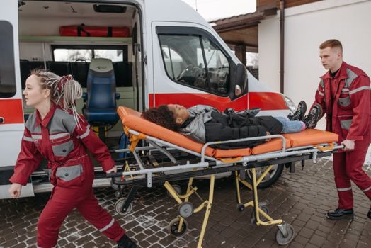
The Stryker Model 6506 Power-PRO is a powered wheeled stretcher with a battery-powered hydraulic lift system intended to support and transport the entire body of a traumatized, ambulatory, or non-ambulatory patient (including infants and adults), and Stryker explicitly directs the certified mechanic to plan the placement of the safety hook in the rear of the vehicle prior to installation [S4]. The non-powered counterpart, Stryker Model 6086 Performance-PRO XT, supports the same patient population in supine or sitting positions and uses a mechanical (non-hydraulic) lift [S5].
The two cots share a vehicle-side interface: floor-mounted track or floor plate, a head-end safety hook that captures the cot under crash deceleration, and a foot-end loading wheel that rides into the ambulance. The powered variant adds a 12 VDC or 24 VDC hydraulic pump, a charging circuit, and a documented battery service interval; the non-powered variant eliminates the pump, valve block, and battery, which is the single biggest reason fleet operators mix the two on the same vehicle. When the comparison comes down to four decision criteria, the split is: (1) lift method — 12/24 VDC hydraulic vs mechanical; (2) patient weight capacity — both rate for adult + infant use, but check the exact model label, not the marketing brochure; (3) vehicle electrical — the 6506 needs a charging circuit and a sealed battery, the 6086 does not; (4) crew-injury exposure — the powered unit is documented to reduce operator lift effort, which is a workers'-comp metric, not a marketing claim [S4][S5].
Acceptance Criteria: When to Sign Off vs When to Reject
For an aircraft kit, sign-off requires the seat-track latches to fully engage (audible click, visual confirmation of the secondary lock), the restraint straps to pass the fraying/cut/seam-deterioration DET, the pad set to be free of contamination that would compromise fireworthiness, and the AF-510 revision status to be at Revision IR or later as listed in the document's log of revisions [S2]. Reject and replace the kit if any attachment fitting shows deformation, any seat-track interface shows elongation of the latch holes, or the restraint webbing shows cuts longer than the limits in the Component Maintenance Manual — the AF-510 "Inspect all attachment fittings and replace if necessary" line is mandatory, not advisory [S2].
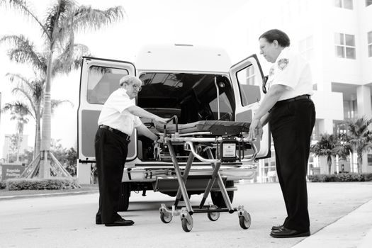
For an EMS cot, sign-off requires the safety hook to capture under a pull test in the direction of vehicle travel, the loading wheel to roll up the ramp without binding, the hydraulic lift (6506 only) to raise and lower under battery power without stalling, and the cot to lock into the vehicle fastener under a push-and-pull test in each axis [S4][S5]. Reject and escalate to Stryker technical support if the safety hook does not capture under load, the hydraulic system shows pressure loss greater than the manual's leak-down rate, or the cot frame shows any crack at a weld. Per the Stryker manual, a certified mechanic is the required installer class, and the safety-hook placement is a planned decision, not a field improvisation [S4][S5].
Common Failure Modes: Symptom, Root Cause, Corrective Action
Symptom — stretcher drifts forward on the seat track during taxi. Root cause — seat-track latch spring fatigued or latch roller worn. Corrective action — replace the latch assembly per AF-510 parts list, do not shim or bend the existing hardware; verify the secondary lock engages under the DET [S2].
Symptom — restraint strap shows surface abrasion but no cut. Root cause — strap routed over a sharp pad-frame edge. Corrective action — reroute the strap per the AF-510 diagram, replace the strap if abrasion exposes the inner load-bearing yarns, and log the finding in the aircraft maintenance records [S2][S3]. Symptom — Stryker 6506 raises slowly or stalls under load. Root cause — battery state-of-charge below operating threshold or hydraulic fluid level low. Corrective action — recharge or replace the battery, top up the hydraulic fluid per the 6506 service manual, and re-test; do not bypass the low-battery cut-out [S4]. When the question is whether to repair or replace, the rule is simple: replace any load-bearing textile, latch, or weld; repair only consumables (fluids, labels, charging fuses) per the manual's parts list.
For a related fixed-installation spec map on ceramics handling and fit, see the zirconia ceramic installation guide. For a parallel track-style industrial reference, the crossed roller guide selection criteria follow the same load-class-and-anchor logic used by the AF-510 seat-track interface. A broader stretcher overview covers both aircraft and EMS product families in the encyclopedia.