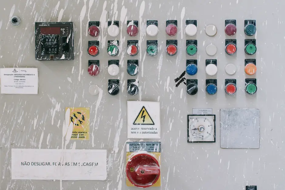
Welding-cell guard doors see more open/close cycles per shift than almost any other discrete-manufacturing cell, which makes the interlock switch the first component to fail on a robotic MIG, spot-weld, or laser-weld station.
The global industrial interlock switch market reached $2.8B in 2025 and is projected to hit $4.9B by 2034 at a 6.4% CAGR, with tongue interlock switches holding 38.5% type share and Asia Pacific at 36.2% regional share [S1]. Welding cells sit inside that envelope, but the spec map narrows quickly once you factor in weld-spatter exposure, heat soak, and the need for category-1/category-3 (Cat. 1 / Cat. 3) or PLe-rated guard-door logic.
What an interlock switch must do on a welding cell
A welding-cell interlock is a safety-critical device designed to prevent machine operation when access doors, guards, or protective covers are open, forming the input leg of the cell's safety control chain [S1]. On a robotic weld cell the device typically drops the robot's safety stop circuit, the weld-enable contactor, and the laser/RF source enable when the door opens.
For laser-weld and hybrid laser-arc cells, the architecture mirrors what Lasermet delivered at NASA Langley Research Center in July 2026: ICS-9 interlock controllers, Safety Logic Plus logic, and a CaLM monitoring system where every entry door, port, and emergency stop must be in a safe state before the laser can be armed [S2]. Welding cells use the same logic backbone, just with different actuator technologies and shorter response-time budgets.
Switch type comparison for welding duty
Five switch families dominate welding-cell specifications, each with a distinct guarding fit. The table below lines them up on the criteria that matter on a weld floor. [S1]
Tongue (mechanical) interlock switches remain the largest type at 38.5% of 2025 market share because of their low cost and positive-opening contacts, but they wear on dirty, spatter-coated doors. Solenoid-locking interlocks (e.g. AZM-series guard-locking devices, 24 V DC spring-applied locking) physically hold the door closed until the machine reaches a safe state, which is the right behaviour on a robot cell where the robot can coast into a pinch point after stop [S3].
Non-contact magnetic and RFID-coded safety sensors deliver SIL3 / PLe ratings without a mechanical actuator, tolerate misalignment, and shrug off weld spatter because there is no slot to clog, with typical IP67 / IP69K sealing [S3]. Hinge-mounted safety switches and rope-pull emergency stops (e.g. RSS 36, bi-directional, IP67) cover long weld-line cells where the operator may need to trip the stop from any point [S3]. Trapped-key interlocks enforce safe isolation sequences on cells with multiple access points, which is the pattern shown in the Safety Interlock Switch Selection for Mining Operations reference case for multi-access heavy equipment.
Selection criteria that actually drive the BOM

Three criteria filter the catalogue faster than any spec sheet. First, the safety performance level: ISO 13849-1 PLd / PLe (or IEC 62061 SIL2 / SIL3) is the operating envelope for robotic weld cells, and the supplier must be able to publish the PFHd, the category, and the diagnostic coverage [S3]. Second, coding level per ISO 14119: uncoded, coded, uniquely coded, or fully coded dictates how easily an operator can defeat the switch with a spare actuator, which is why welding cells with contract labour typically mandate at least a coded actuator. Third, sealing: IP67 is the floor for any switch within 1 m of a weld spatter plume, and IP69K is the right pick for cells that get steam-cleaned between shifts [S3].
Two secondary criteria quietly drive cost. Positive-opening contacts (per IEC 60947-5-1) are mandatory on mechanical switches used in safety circuits, and they are what separate a true safety switch from a standard limit switch in the same housing [S3].
Who this spec is for, and who it is not for
Welding-cell interlock selection is built for plants running robotic MIG, spot-weld, stud-weld, or laser-weld cells with interlocked light curtains or perimeter fencing, where a Category 1 or Category 3 stop circuit must drop within milliseconds of door opening. The reference architecture in Safety Interlock Switch Selection for Chemical Plants: Spec Map shares the same switching logic but layers ATEX/IECEx zoning on top, which is overkill for a non-classified weld booth. [S3]
It is not the right map for simple manual welding bays without powered guarding, for cobot cells where the inherent safe-design approach replaces perimeter interlocks with power-and-force limiting, or for hand-held laser cladding where the operator controls the energy source directly. For those, the gating device is usually a keyed enable switch or a three-position enabling device (SIL3 / PLe, IP54 / IP65) [S3], not a guard-door interlock.
Failure modes and operating limits specific to weld cells

Three failure patterns show up repeatedly in field returns. Weld spatter fouling of the actuator slot is the dominant mechanical-tongue failure, and the field fix is either a stainless shroud or a step up to an RFID-coded non-contact sensor. Heat soak above 70 deg C at the switch body causes plastic-housed devices to creep and lose the positive-opening gap, so metal-housed switches (rated to 100 deg C) are the conservative pick for cells adjacent to a weld-torch re-stand. Inductive noise from the weld inverter can corrupt magnetic-coded sensors on long unshielded cable runs; the spec must call for a twisted-pair run and an M12 connector with proper shielding, or the sensor drifts into a fault state. [S3]
Lasermet's 2026 NASA Langley install illustrates a parallel welding-style logic: every port is fitted with interlock switches, selector controls, and warning indicators, and the system automatically returns to 'Safe Mode' and requires re-arming if a port is reselected [S2]. Welding cells need the same auto-rearm logic so a door-open event during a fault-clear sequence does not leave the cell in a hidden armed state.
Standards and sourcing that govern the build
The governing framework for European-built weld cells is the Machinery Directive 2006/42/EC, with OSHA 29 CFR 1910.217 covering the U.S. equivalent for mechanical power presses, both cited as the regulatory drivers behind current retrofit demand [S1]. Device-level compliance is normally proven against ISO 14119 (interlocking devices), ISO 13849-1 (PL a-e), IEC 62061 (SIL 1-3), and IEC 61496 for any light curtain that shares the safety circuit, with Type 4 light curtains being the conservative pick for weld cells [S3]. The supplier audit trail should show the test certificates, the PFHd figure, and a Declaration of Conformity that names all four standards together; a single-standard declaration is a red flag.
Schmersal's channel-partner documentation, for example, lists SIL3 / PLe capability and ISO 13849 / IEC 62061 certification across its safety-switch and solenoid-interlock lines, including the AZ 200 coded-actuator series, the AZM 200 STS guard-locking series, the RSS 36 rope-pull series, and SRB / SRR safety relays [S3]. The same document also tags every device as genuine, manufacturer-warrantied, and supported with pre-sales consultation, which is the baseline any weld-cell spec should require before cutting a PO.
Decision snapshot: which switch for which cell
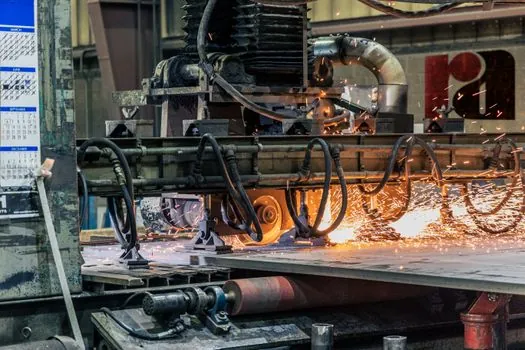
For a high-cycle robotic spot-weld cell with a single operator door, a solenoid-locking interlock (24 V DC spring, Cat. 3, PLd) is the baseline. For a laser-weld cell with multiple ports and a touchscreen HMI, the right topology is a safety logic controller (ICS-9 or equivalent) fronting RFID-coded non-contact sensors on every port, with the cell wired so any reselect returns the system to Safe Mode [S2]. For long linear weld lines, a bi-directional rope-pull emergency stop (IP67) at each operator station plus magnetic-coded non-contact sensors on the access doors covers both trip-from-anywhere and guard-monitoring duties [S3]. For contract-cleaned food-grade or pharma weld cells, IP69K-rated non-contact RFID sensors are the only switches that survive daily washdown without sealing failure.
Track the next signal: a published revision of ISO 14119's coding-level table, and any 2026 supplier release of IO-Link diagnostics on safety switches that lets the cell's PLC log every guard-open event with a millisecond timestamp instead of a binary input. Either of those would shift the BOM and the spec map within the next two budget cycles.
The underlying component specifications are covered under safety interlock switch, welding cutting tool, and fire safety.