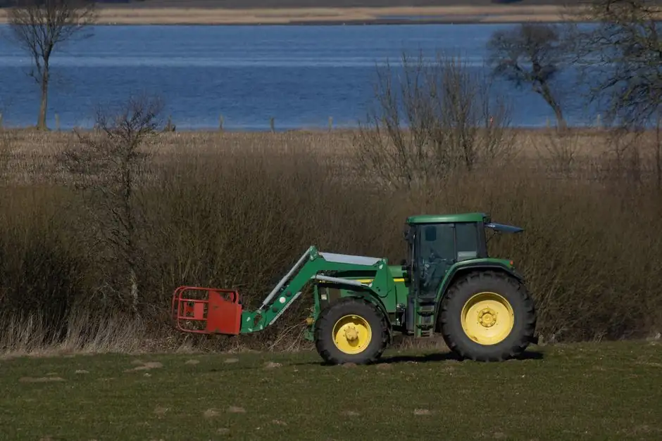
A wheel loader is a four-wheeled, articulated machine that scoops material with a front-mounted bucket, lifts it via a hydraulic boom and rocker-arm linkage, and dumps it into a truck or hopper, all driven by a diesel engine coupled to a torque converter and a split hydraulic system [S2].
For sizing reference, large-class wheel loaders can carry up to 18 tons per pass, and the bucket cylinder in a Z-bar geometry also serves as the primary breakout actuator [S4][S5]. The working device is a four-bar mechanism (boom, rocker arm, bucket, pull rod) on a hinge-pinned front frame, with the rear frame steered by two hydraulic cylinders for tight-site maneuverability [S2][S3].
Power System: Diesel Engine, Torque Converter, Transfer Case
The diesel engine is the prime mover and is paired with a torque converter that multiplies output torque against rising load, then feeds a powershift gearbox and a drive shaft to the front and rear axles [S2]. The same engine drives a transfer-case-mounted hydraulic pump, which feeds both the working hydraulics (boom, bucket, steering) and the steering hydraulic circuit [S2][S3]. During a dig cycle the converter lets the machine cut into the heap at high speed, then automatically decelerate as resistance rises, so tractive effort climbs without operator shifting [S2]. This is why a wheel loader can start on a slope, cross a sudden obstacle, and still pull through without a manual downshift: the torque converter absorbs the speed/torque trade-off between engine and wheels [S2].
Transmission and Driveline: Torque Converter to Four Wheels
The transmission system consists of a torque converter, gearbox, drive shaft, front and rear drive axles, and wheels; it auto-adjusts output torque and speed to match road conditions and resistance, giving stepless variation from start to top speed [S2]. Engine output flows: engine to torque converter, through the gearbox for ratio selection, via the transmission shaft to the front axle (and rear axle on 4WD models), then to the wheels [S2][S3]. The converter's stall-torque multiplication is what gives a wheel loader its characteristic crowd-and-lift behavior: high wheel speed for the approach, then a rapid torque rise as the bucket bites the pile [S2]. Compared with a skid-steer loader, which steers by differential side-to-side wheel speed, the wheel loader uses an articulated frame pivot, so it preserves straight-line tractive effort while still turning inside a small radius [S1].
Working Device: Boom, Rocker Arm, Bucket, Pull Rod
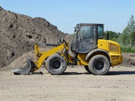
The working device is a four-part linkage: bucket, arm (boom), rocker arm, and pull rod, hinged to the front frame, with two hydraulic cylinders (boom cylinder and bucket cylinder) driving it [S2][S3]. The boom is a single-plate structure, pinned at the rear to the front frame, with the bucket on the front end and the boom cylinder attached in the middle; extending the boom cylinder rotates the boom about its rear pin and lifts the bucket [S2]. Bucket rotation is a separate motion: the bucket cylinder extends/retracts a single rocker arm pivoting about its mid-support, and the rocker arm pulls a connecting rod to roll the bucket up or down [S2][S3]. This separation of lift and tilt is what allows an operator to float a load, dump at height, or hold a level carry without complex valve work [S1][S2].
Linkage Geometry: Z-Bar vs. Parallel-Lift
The two dominant arm geometries on production wheel loaders are Z-bar linkage and parallel-lift linkage, and the choice directly trades breakout force for load-leveling visibility [S4]. A Z-bar linkage connects the bucket through a bucket cylinder, two bucket links, and a center bellcrank, forming the literal Z that gives the design its name; it is the original, simpler geometry with greater raw digging power but a bellcrank that partially blocks the operator's view of the bucket, and the bucket naturally rotates as the boom raises [S4]. A parallel-lift linkage splits the bucket cylinder's job across two cylinders, one on each boom arm, and uses multiple links so the bucket stays parallel to the ground through the lift arc, which is preferred for fork work and palletized loads but adds parts and slightly reduces breakout force [S4]. For spec-first buyers weighing the two, the decision is essentially: Z-bar for quarry/aggregate face shoveling, parallel-lift for logistics yards and rehandling with forks [S4].
Hydraulic and Steering Systems
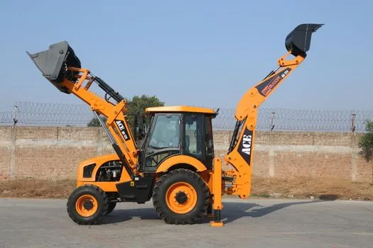
On a wheel loader the working hydraulic system powers the boom and bucket cylinders, while a separate steering hydraulic system drives two cylinders mounted across the articulation joint, deflecting the front and rear frames about a central hinge pin [S2][S3]. The frame itself is split into a front section and a rear section joined at the middle by a hinge pin, and the steering cylinders rotate the two halves relative to each other to change direction [S3]. Because the same engine-driven pump supplies both circuits, sustained full-pressure digging at high engine load can starve steering response on older machines; modern loaders address this with load-sensing or dual pumps, though specific pump displacements vary by OEM and were not confirmed in the source material [S2]. The cab, electrical system, panel, and air conditioning are auxiliary to the core five systems (power, transmission, working device, working hydraulics, steering hydraulics) that determine the machine's working behavior [S2].
Operating Cycle: Dig, Lift, Carry, Dump
A complete wheel loader cycle is dig, lift, carry, and dump, with the operator modulating bucket roll and boom height independently through the joystick-controlled proportional valves [S1][S5]. The bucket is driven into the pile under tractive effort, rolled back with the bucket cylinder to retain the load, then the boom cylinder raises the load to carry height; mid-air, the operator can adjust bucket position to rebalance the load before driving to the dump target [S1][S5]. For narrow or confined sites where the machine cannot turn to face a truck, a swing loader variant uses a boom that rotates more than 180 degrees to load from either side, while a backhoe loader adds a rear excavator arm for digging and backfilling in one chassis [S1]. In waste, slag, and bulk-material applications (rehandling, slag transport, snow removal, pipe laying) the same four-step cycle is the workhorse, and the choice between a permanently fixed bucket and a quick-coupler attachment fleet is the main field configurability knob [S1][S5].
Comparison: Wheel Loader vs. Other Loader Classes
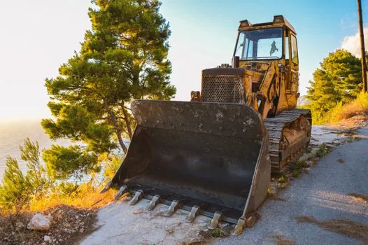
Across loader types, mobility, ground pressure, and dig geometry differ enough that the wheel loader is not a one-for-one substitute for tracked or compact machines [S1]. The table below lines up the four main competing classes on the criteria that drive equipment selection for engineers and site planners.
Wheel Loader: four wheels, articulated steering, largest loader class, suited to flat solid surfaces, bucket breakout via Z-bar or parallel-lift, mobility is highest on hard surfaces, ground pressure is moderate and non-damaging to asphalt [S1]. Skid Steer Loader: compact, side-boom layout, differential steering, ideal for narrow spaces, lower capacity than a wheel loader but trades raw size for access [S1][S3]. Tracked Loader: track undercarriage, superior off-road stability on soft, muddy, or uneven ground, lower surface speed, used where wheeled machines bog down [S1]. Backhoe Loader: hybrid with a front loader bucket plus a rear digging arm, used for trenching and backfilling in a single pass [S1]. For a fleet planning decision, the wheel loader wins on haul speed and bucket capacity, the skid-steer wins on access, the tracked loader wins on soft ground, and the backhoe loader wins on combined dig-and-load versatility [S1].
Use Cases, Limitations, and Sourcing Signals
Wheel loaders are specified for block and bulk material handling, log handling in forestry, rock loading in quarries and mines, landfill and waste-recycling work, slag transport in steel mills, road and railway construction support, and snow or rubble clearing [S1][S3]. Limitations: wheeled undercarriage is the wrong tool for soft, waterlogged, or steeply uneven ground, where a tracked loader or excavator outperforms it; the front-bucket reach is limited compared to a telescopic handler; and articulated steering, while tight, still requires a turning radius the operator must plan around on congested sites [S1]. The wide range of attachments (forks, grapples, snow blades, sweepers) is the main lever for fitting a single chassis to multiple jobs, and quick-coupler hydraulic lines are now standard on most production units [S1][S5]. The global wheel loader market is tracked as a high-volume construction-machinery segment, with analysts estimating it will reach a value of over $23 billion by 2030, per public industry reporting [S5]. Trackable signals for buyers: confirm whether the working pump is load-sensing (not stated in source material), confirm Z-bar vs. parallel-lift geometry on the nameplate, and verify that articulation-pin ground clearance suits the site's slope before delivery, since these are the three spec gates that drive real on-site productivity rather than advertised engine power [S1][S2][S4].
The underlying component specifications are covered under wheel loader.
This topic is covered further in Pneumatic Actuator Pros and Cons: A Spec-First Decision Map.