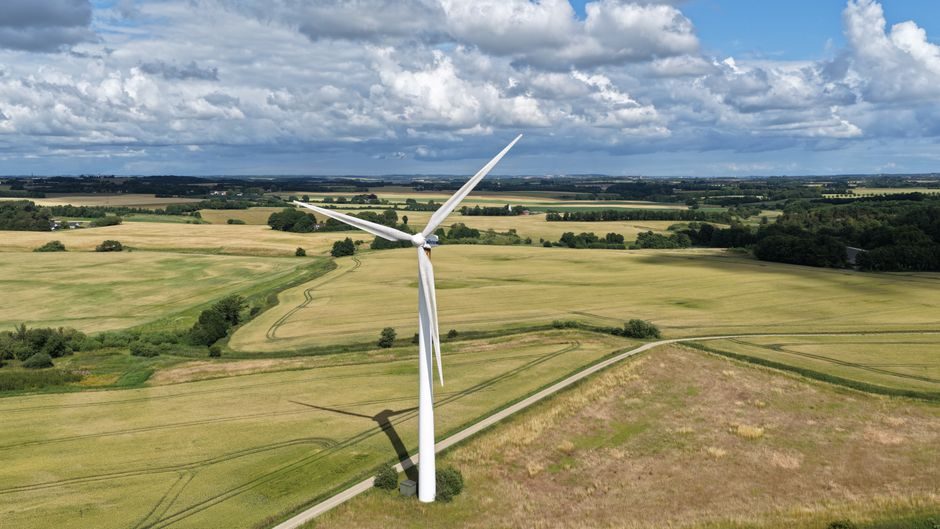
A utility-scale horizontal-axis wind turbine (HAWT) is a 200–300 tonne steel-and-composite assembly that decomposes into roughly four BOM tiers — rotor, drivetrain, nacelle, and tower/foundation — with the longest single component now standing at 131 m for onshore units [S1].
Each tier has its own material logic: blades are predominantly glass-fibre reinforced polymer (GRP) with carbon-fibre root and spar-cap reinforcements on large machines [S2]; the tower is welded plate steel; the drivetrain is forged and case-hardened steel. Together the BOM typically runs 8,000–15,000 line items when the LV cable runs, fasteners, and consumables are counted [S3].
Rotor Tier: Blades, Hub, Pitch System, Nose Cone
The rotor assembly is the most material-intensive section of a modern turbine BOM, and a 131 m single-piece onshore blade set produced at Bayannur, Inner Mongolia on 2024-03-22 is the current size benchmark [S1]. Each blade runs 50–70 tonnes for a 100+ m unit, with the three-blade hub assembly adding another 70–120 tonnes of ductile iron or cast steel.
Composite lay-up follows a sandwich construction: GRP skins over PVC or PET foam or balsa core, with unidirectional carbon plies concentrated in the spar cap and root [S2]. The pitch system on each blade contributes hydraulic or electric actuators, a bronze or steel bushing ring, and a PLC-driven pitch drive; redundant accumulators are standard for E-stop requirements. Total rotor part count including fasteners, lightning receptors, and de-icing mats is typically 600–1,200 items per blade [S3].
Drivetrain Tier: Main Shaft, Gearbox, Generator, Couplings
The drivetrain BOM centres on a forged 42CrMo4 or 34CrNiMo6 main shaft running in two spherical-roller bearing housings, a multi-stage planetary-helical gearbox (typical ratio 1:120–1:200 on a 3 MW class unit), and a doubly-fed induction generator (DFIG) or permanent-magnet direct-drive generator. Gearbox stages are typically 1 planetary + 2 helical, with case-hardened 16MnCr5 / 18CrNiMo7-6 gears grinding-finished to ISO 1328 grade 6 or tighter. [S1]
Direct-drive designs eliminate the gearbox but substitute a heavier, larger-diameter PMG (often NdFeB magnets over a copper or aluminium winding) and push nacelle mass 40–60 t higher than a geared equivalent. The brake system pairs an aerodynamic pitch shutdown with a hydraulic yaw-calliper disc brake on the high-speed shaft, sized for the full torque-load. Couplings are typically flexible diaphragm or gear-type, with torque ratings matched to gearbox peak torque [S3].
Nacelle Auxiliaries: Yaw, Pitch, Converter, Controller, Sensors
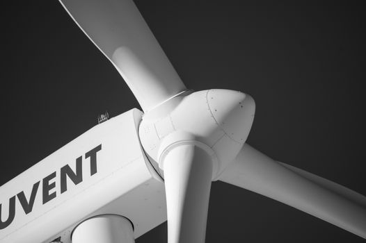
A nacelle BOM breaks out into roughly nine sub-assemblies: yaw system (4–6 slew drives with slewing-ring bearings), pitch system (3 drives), converter cabinet, transformer, controller cabinet (PLC + SCADA), hydraulics or e-pitch accumulators, cooling package, sensors, and the nacelle housing itself (a GRP or steel canopy on a welded base frame). [S2]
Pitch and yaw slewing rings are 4-point-contact ball bearings, usually 1.5–3.5 m bore, with induction-hardened raceways. The converter is a back-to-back IGBT stack with a DC-link choke and LV filter, typically 690 V AC output stepped up by an internal or pad-mount transformer to 10–35 kV for collection. Controller architecture is PLC-redundant (commonly Bachmann or Beckhoff) with a vibration-monitoring module tied to the SCADA gateway, and the controller cabinet itself is often a 316L stainless or powder-coated steel enclosure rated IP54–IP65 [S3]. Flow-measurement and pressure transmitter channels feed the hydraulic pitch and lubrication loops; vibration on the main bearing is read through IEPE accelerometers, while rotor speed and position come from a multi-channel encoder and a yaw-angle sensor.
Tower and Foundation: Steel Plate, Bolts, Embedment, Rebar Cage
The tower is a tapered conical shell of welded S355NL or S460NL plate, 4–6 sections for a 100–160 m hub height, joined at L-flanges with preloaded 10.9-grade bolts (typically M36–M64, quantity 80–200 per flange). Wall thickness scales from ~30 mm at the base ring down to 8–14 mm at the top, with the door-frame section reinforced by a D-collar. [S3]
The foundation is a gravity-spread footing — roughly 600–1,200 m³ of C30/37 or C35/45 reinforced concrete, a 80–150 t rebar cage (B500B or B500C), and a conic or cylindrical embedment ring with anchor bolt cages. For a 5 MW onshore unit the total concrete pour commonly lands in the 700–900 m³ band. Foundation rebar specifications typically include a yield strength of 500 MPa, splice lengths per EN 1992-1-1, and concrete cover of 50–75 mm depending on exposure class [S3].
Material and Standard Map Across the BOM
Material selection splits cleanly by tier: GRP/CFRP composites dominate blades; forged and case-hardened alloy steels (42CrMo4, 16MnCr5) dominate the drivetrain; structural plate steel (S355/S460) dominates the tower; reinforced concrete dominates the foundation. Fasteners are uniformly 10.9 or 12.9 grade, preloaded and torqued per EN 14399 for HV sets on the tower flange. [S4]
Standards mapping: tower steel is commonly delivered to EN 10025-3/-4, gear steel to EN 10084, blade composites to DNVGL-ST-0376 (Rotor blades for wind turbines), and the complete machine is type-certified to IEC 61400-1 design classes (I–III for onshore, S for offshore special). The IEC 61400-27-1 event-based simulation model and the IEC 61400-25 communications standard govern the SCADA interface; condition-monitoring data exchange typically follows IEC 61400-25-2 mappings [S3].
Failure Modes That Drive Spare-Part BOMs
Drivetrain bearings and gearbox stages account for the largest single share of unplanned downtime on multi-MW turbines, with main-shaft bearing replacement windows of 5–10 years and gearbox oil-change intervals of 12–24 months on a 3 MW class unit. Blade leading-edge erosion, lightning strike damage, and pitch-bushing wear are the top rotor-side failure drivers; controller and converter IGBT failures dominate nacelle-side downtime. [S5]
Sourcing a robust spare-parts BOM therefore concentrates inventory on: main-shaft and gearbox bearings, a spare gearbox, pitch motor/accumulator sets, IGBT modules, industrial valve spares for the hydraulics, slewing-ring segments, and a small stock of consumable composite repair kits. Specialty repair vendors handle controller refurbishment and tower section bolt replacement on-site, with a typical 5–10 year overhaul cycle covered under a service agreement [S4].
Trackable Sourcing Signals
Three signals to watch: Chinese onshore blade capacity continues pushing beyond 130 m single-piece, with the 131 m Bayannur line operating since 2024-03 [S1]; a separate hub cluster of large-bore slewing-ring forging in Yingkou and Dalian is the dominant supply for nacelle yaw systems; and offshore direct-drive PMG designs are pulling demand for rare-earth NdFeB segments. Buyers can track blade line announcements, slewing-ring inventory at Yingkou forgers, and NdFeB magnet export figures as leading BOM-cost indicators.
For related coverage, see Truck-Mounted Concrete Pump Picks for Oil and Gas Sites: 2026 Spec Map.