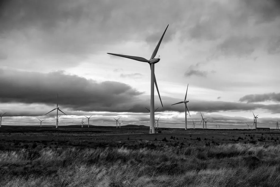
Wind turbine gearbox production planning has shifted from per-unit quotas to per-megawatt throughput, driven by an industry move from 2-3 MW onshore and 5-6 MW offshore machines toward 10-12 MW offshore units that each consume hundreds of tonnes of gearbox, generator, and structural mass [S1].
Procurement teams sizing 2026 and 2027 capacity must therefore plan against torque density, not nameplate count. ZF Wind Power, one of the two dominant geared-drivetrain suppliers alongside the Vestas in-house line, has crossed 10 GW of shipped offshore capacity through its collaboration with Vestas, and now operates a 30 MW test rig at its Test & Prototype Center to validate complete onshore and offshore powertrains before series release [S3]. For spec-driven buyers, this is the practical scale reference: a single modern offshore turbine's geared drivetrain is roughly 200-320 t for a 10 MW unit, and that mass must clear road, bridge, and crane limits before production rates can be lifted [S1].
Capacity Sizing: Match Output to Turbine Class, Not Unit Count
Gearbox production capacity is now quoted in megawatts of rated fleet supported per quarter, because the same factory that delivered 50 units of 3 MW gearboxes in 2018 must now deliver perhaps 12-15 units of 10 MW gearboxes for the same megawatt throughput, with each unit carrying far higher forging, heat-treatment, and assembly hours [S1][S3].
For onshore planners, the 2-3 MW class remains the volume backbone and tends to dominate gearbox factory utilisation in 2026 builds, while offshore planners must reserve dedicated lines for 10-12 MW units that demand larger test rigs, heavier lifting, and longer cooling-system validation cycles [S1]. A practical sizing rule of thumb circulating in drivetrain engineering is that the factory's gearbox test bench should be rated at 2-3 times the largest single-unit power class, which is exactly the headroom ZF built into its 30 MW rig relative to current 10-12 MW commercial designs [S3]. Buyers can read more on drivetrain architectures in the gearbox encyclopedia entry, which covers the planetary and helical stages that dominate this segment.
Selection Criteria for 10 MW Class Gearboxes
Three engineering criteria now govern whether a gearbox supplier can deliver against a 10-12 MW production plan: torque-per-stage density, thermal management under partial-load duty, and modularity for field replacement without nacelle removal. [S5]
On density, the trend is to keep mass below the 200-320 t envelope flagged for a 10 MW generator system, which forces designers to lean on simulation-driven thermal and load work rather than brute-force scaling [S1][S4]. On thermal management, ZF Wind Power replaced spreadsheet-based flow-network sizing with Siemens Simcenter Flomaster, because the lubrication distribution on a multi-megawatt gearbox can involve hundreds to thousands of small components, each contributing pressure losses that determine bearing and gear-mesh temperatures [S4]. On modularity, the cartridge-style gear set, in which each generator stage is pre-assembled as a drop-in module, lets crews replace a stage without pulling the entire drivetrain, and remains the field-service benchmark published in OEM service documentation [S9]. Buyers who need a quick comparison of flow-element choices that feed into these lubrication and cooling loops can refer to the flow meter overview, since lube-circuit flow verification is a documented acceptance test on most 10 MW class units [S4].
Comparison of Main Drivetrain Options for Capacity Planning
For a 10 MW class turbine in 2026, the three credible drivetrain choices are: a multi-stage planetary plus helical geared drive (the volume incumbent), a permanent-magnet direct-drive generator (no gearbox, higher generator mass), and a hybrid or integrated mid-speed geared design. Each has a different impact on gearbox production capacity because each places the constraint on a different subassembly. [S5]
On cost and supply risk, the geared multi-stage path has the deepest supplier base and the lowest unit mass at the gearbox, but carries the highest gearbox failure rate, which is the single largest driver of spare-unit inventory [S1][S5]. On weight and tower-head loading, the direct-drive path removes the gearbox but adds permanent-magnet material content (neodymium, dysprosium) and a heavier generator, which inflates tower and foundation cost on every unit [S1]. On lifecycle O&M exposure, hybrid mid-speed designs sit in the middle but compress the spare-parts list because fewer stages carry the torque, and they are increasingly specified for floating offshore where nacelle mass is the binding constraint [S1][S5]. For buyers cross-checking instrumentation choices that tie into the gearbox supervisory loop, the pressure transmitter reference covers the lube-circuit pressure sensing that is standard on 10 MW class units [S4].
Reliability and Lead-Time Planning Inputs
Lead times for replacement gearboxes are the swing factor in any 2026 capacity plan, and they are driven by bearing and gear-mesh failure rates that show up in dynamic reliability models rather than static fatigue calculations [S5][S6][S7].
Static and fatigue calculations under AGMA-style or ISO 6336-style methodologies remain the baseline for design verification, but they do not capture real-time load spectra on a turbine operating in partial-power regions, which is why dynamic reliability estimation against live operating-condition data has moved into production planning conversations since 2025 [S6][S7]. A practical planning input is that gearbox issues create long outages that bundle crane waiting time, crew mobilisation, and lost generation, and the dominant mitigation is a documented proactive monitoring program plus a stocked replacement unit, not a faster field repair [S5]. Buyers evaluating condition-monitoring hardware for this loop can compare sensing options in the pressure sensor entry, since lube-line pressure is one of the standard channels watched on multi-megawatt units [S5][S6].
What Production Capacity Planning Is For, and What It Is Not
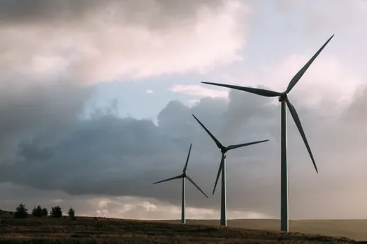
Capacity planning is for procurement, operations, and engineering teams who need to commit factory slots, spare-unit inventory, and crane windows against a known 10-12 MW build pipeline; it is not for speculative forecasting of turbine counts without a confirmed power-class mix, because the per-unit labour and floor-time differ by a factor of roughly three between a 3 MW and a 10 MW gearbox [S1][S3].
Operators running 2-3 MW onshore fleets in 2026 can still use count-based capacity models, but anyone touching the offshore pipeline should rebase to megawatts and lock at least one qualified 10 MW class supplier with documented test-rig headroom, because the alternative is a 12-18 month wait for a replacement gearbox when a single bearing event takes a unit out [S3][S5]. A useful sanity check before committing is to ask the supplier for the rated power of its largest test bench and the cumulative shipped capacity of its current platform, since both numbers are now published on OEM product pages and are the closest proxy for whether the supplier can absorb a production-rate step-up [S3]. For adjacent process-engineering context, see the recent spec snapshot on wind turbine blade Industry 4.0 adoption, which covers the same factory-throughput questions from the blade side of the nacelle.
Failure Modes and Constraints That Bind the Plan
The three binding constraints on 2026 gearbox capacity are nacelle mass at the 200-320 t level for 10 MW units, lubrication-circuit pressure loss across hundreds of distribution components, and the throughput of the largest validation test bench available to the supplier [S1][S3][S4].
Each constraint can be planned against: mass is bounded by road and crane limits, which sets a hard ceiling on how much steel can leave the factory per quarter; lubrication pressure loss is bounded by the supplier's simulation maturity, which determines how many cooling-iteration prototypes must be bench-tested before release; and test-bench throughput is bounded by the rated power of the rig, with ZF's 30 MW rig setting a public benchmark that competing suppliers now have to match or exceed for 10-12 MW class orders [S3][S4]. Operators should also note that gearbox failure rates drive spare-unit inventory more than any other subsystem, so the production plan should explicitly reserve a fractional throughput for service replacements rather than treating spares as an afterthought [S5][S6].
Two trackable signals to watch over the next two quarters: any OEM announcement of a test rig rated above 30 MW, which would be a leading indicator of 15 MW class commercial production planning, and any disclosed move by a supplier to license or acquire gearbox forging capacity, which is the bottleneck that has historically capped throughput for 10 MW class units [S3][S4].